
Logic probe

The circuit employs a configuration of PNP transistors to create a buffer and a level detection mechanism. The buffer formed by Q1 and Q2 ensures that the input impedance remains high, which is essential for accurate signal probing without loading the circuit. This is particularly important in sensitive applications where the probe must not influence the circuit under test.
The level detection functionality is achieved through the combination of Q3 and Q4. When the input voltage at the base of Q3 exceeds the threshold of 0.6 V, Q3 transitions from the cutoff region to the active region, allowing current to flow from the collector to the emitter. This action activates Q4, which is also a PNP transistor, resulting in the illumination of the red LED, indicating a high voltage condition.
Similarly, Q5 and Q6 are configured to detect lower voltage levels. When the input voltage drops to 0 V, Q5 activates, turning on Q6 and illuminating the green LED, signaling a low voltage condition. This dual-LED indication system provides clear visual feedback regarding the voltage levels present at the probe.
The selection of general-purpose silicon transistors such as BC178 for Q1, Q4, and Q5, and BC108 for Q2, Q3, and Q6, ensures that the circuit can handle the necessary current and voltage levels while maintaining reliability and performance. The defined voltage thresholds of 0 V for low and 2 V for high are critical for the proper functioning of the level detection circuit, allowing it to effectively differentiate between high and low states.Transistors Q1 and Q2 form a buffer, providing the probe with a reasonable input impedance. Q3 and Q4 form a level detecting circuit. As the voltage across the base-emitter junction of the Q3 rises above 0,6 V the transistor turns on thus turning on Q4 and lighting the red (high) LED. Q5 and Q6 perform the same function but for the green (low) LED. Ql, Q4, Q5 are all PNP general purpose silicon transistors (BC178 etc) Q2, Q3, Q6 are all PNP general purpose silicon transistors (BC 108 etc) The threshold low is 0 V, and the threshold high is 2 V.
Related Circuits
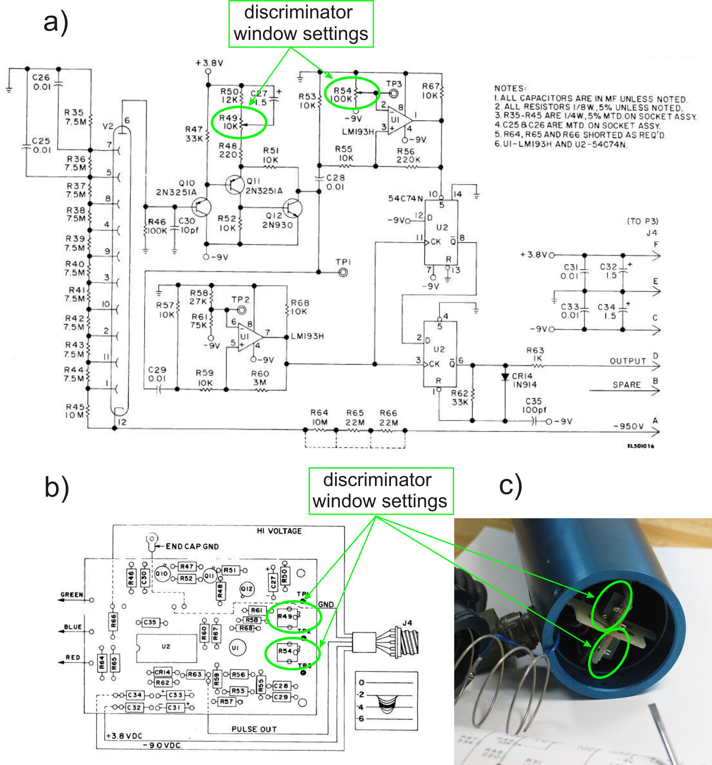
This PDF file presents the schematic diagram of a custom-built circuit designed to drive the PDR-56 probe. A JKL BXA-12579 inverter, typically used for powering cold-cathode fluorescent lamps, serves as the high-voltage power supply. The BXA-12579 generates 1,500 VAC...
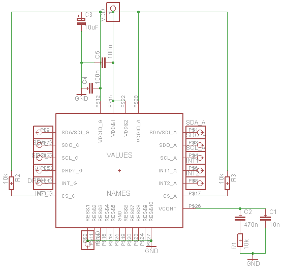
Establish communication between the microcontroller unit (MCU) and the accelerometer using either I2C or SPI protocols. It has been noted that shorting the phase-locked loop (PLL) filter input in the device does not affect the readings from the gyroscope...
A simple voltage probe circuit is depicted in the schematic diagram below. This circuit is highly useful for testing or troubleshooting discrete or integrated circuits. The simple voltage probe circuit serves as an essential tool for engineers and technicians engaged...

Using inexpensive components, you can fit a simple probe circuit into a pencil-sized enclosure. When both LEDs are on, the probe indicates the presence of an ac voltage; either LED alone indicates the presence and polarity of a dc...
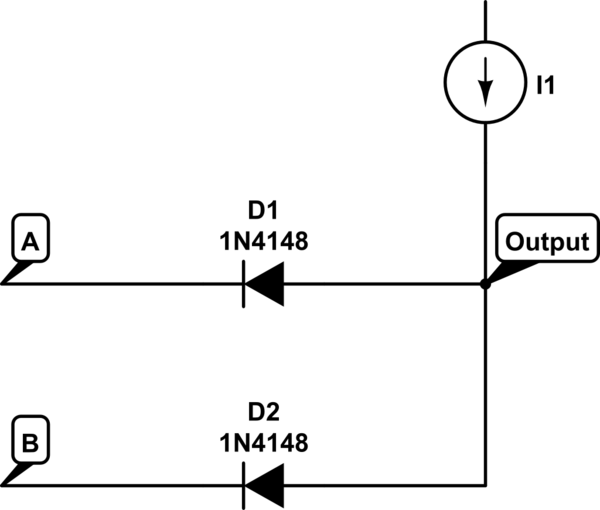
The voltage at the anode and cathode of the diodes is checked to determine whether they are conducting. There is confusion regarding the current source and how to determine the state of the diodes for input combinations (00, 01,...
All of my turbine starts before the research on the ECU involved a very successful spark ignition. I thought (only briefly) of trying to add spark ignition to the ECU, but the mixture of delicate logic circuitry and perhaps...