
A Regularly Repeating Interval Timer

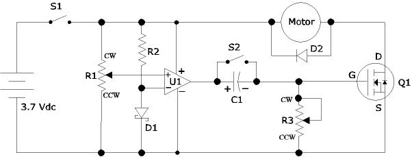
The adjustable output timer circuit typically employs a combination of resistors, capacitors, and an integrated timer IC, such as the NE555 or a microcontroller, to achieve the desired timing functionality. The circuit's core operation is based on the charging and discharging cycles of a capacitor, which, when paired with a resistor, defines the timing intervals.
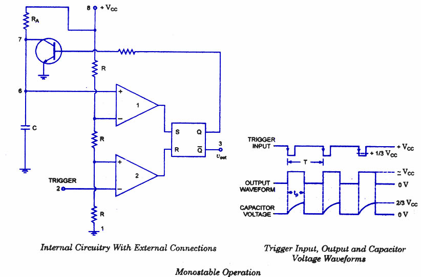
To configure the output duration, the values of the resistors and capacitors can be adjusted. The timer IC is set in either astable or monostable mode, depending on whether a continuous pulse or a single pulse is required. In astable mode, the circuit continuously oscillates, producing a square wave output, while in monostable mode, it generates a single output pulse upon triggering.
For longer timing intervals, larger capacitor values or higher resistance values are utilized. Additionally, the circuit can incorporate features such as a potentiometer to allow for fine-tuning of the timing settings. Output can be connected to various loads, such as LEDs, relays, or other electronic devices, enabling applications in automation, signaling, or timing control.
In applications where precise timing is crucial, the circuit may also include a crystal oscillator for improved accuracy, or it may be integrated into a microcontroller system for more complex timing and control capabilities. Such flexibility makes this adjustable output timer circuit suitable for a wide range of electronic projects and real-world applications.This circuit has an adjustable output timer that will re-trigger at regular intervals. The output period can be anything from a fraction of a second to half-an-hour or more - and it can be made to recur at regular intervals of anything from seconds to days and beyond 🔗 External reference
Related Circuits
Engineer Radu Preda from Romania has developed two energy-saving lighting circuits designed to control the duration that lights are activated, ultimately aiming to reduce electricity expenses. The first circuit utilizes a relay, while the second employs an optoisolator triac...
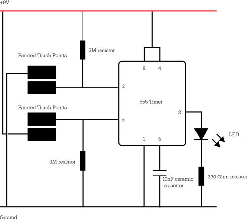
The 555 timer IC was first introduced around 1971 by the Signetics Corporation as the SE555/NE555 and was referred to as "The IC Time Machine." It was the first commercially available timer IC, providing circuit designers and hobbyists with...
Are you familiar with the basics and applications of the 555 timer IC? Are you looking for a book that provides all these basics? If so, CircuitsToday has started an online store where you can purchase books on the...
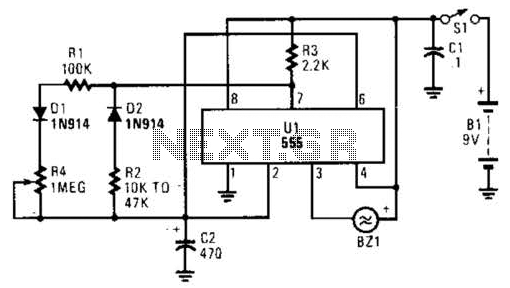
This timer circuit utilizes a 555 IC timer in conjunction with three 74LS193 counters to control an LED display. The circuit is activated by one individual who turns on the piezo buzzer BZ1 through Q1, simultaneously starting the timer....
The following circuit illustrates an Airplane Flight Timer Circuit Diagram. Features include switches in the closed position and battery voltage maintained at a safe level. The Airplane Flight Timer Circuit is designed to provide a reliable timing mechanism for monitoring...
Ensure that connections are verified against the circuit diagram and schematic provided below. This can be utilized while following the tutorial video. The circuit diagram serves as a crucial reference for accurately assembling electronic components in a project. It illustrates...