Reflex Timer Circuit
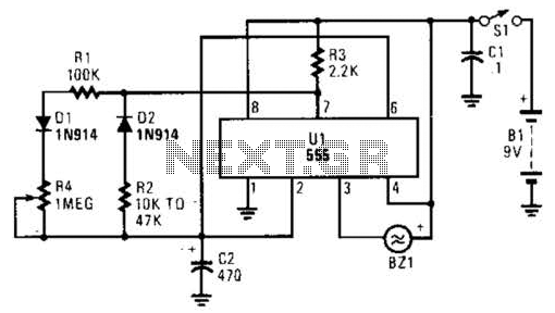
This timer circuit utilizes a 555 IC timer in conjunction with three 74LS193 counters to control an LED display. The circuit is activated by one individual who turns on the piezo buzzer BZ1 through Q1, simultaneously starting the timer. The second individual being timed activates the circuit. Once the timing is complete, the timer shuts off, and the number of lit LEDs represents the elapsed time in binary format.
The timer circuit is designed to provide a visual representation of elapsed time using an LED display, driven by the binary output of the 74LS193 counters. The 555 timer is configured in a monostable mode, which means it will produce a single output pulse when triggered. This output pulse starts the timing sequence, which is crucial for measuring the duration for which the second individual is engaged.
The 74LS193 counters are asynchronous up/down counters that can count in both directions. In this application, they are utilized to count the number of clock pulses generated by the 555 timer. The output of these counters is directly connected to an array of LEDs, where each LED corresponds to a specific binary digit. As time progresses, the counters will increment, lighting up the corresponding LEDs to show the elapsed time in binary format.
The piezo buzzer BZ1 serves as an audible indicator that the timer has started. It is activated by Q1, which acts as a switch controlled by the first person's action. Once the second individual completes their task, the timer circuit is designed to shut off automatically. This is achieved by using a reset mechanism within the counters, which is triggered at the end of the timing period.
The use of binary representation for the elapsed time allows for a more compact and efficient display of information, suitable for applications where space is limited or a quick assessment is necessary. This circuit can be applied in various scenarios, such as sports timing, cooking timers, or any situation where elapsed time needs to be measured and displayed visually and audibly. This timer circuit uses a 555 IC timer and three 74LS193 counters to drive an LED display. SI is activated by one person, who turns on piezo buzzer BZ1 via Ql and also starts the clock; SI is activated by the other person being timed. This shuts off the timer, and the number of LEDs lit indicate, in binary form, the elapsed time.
