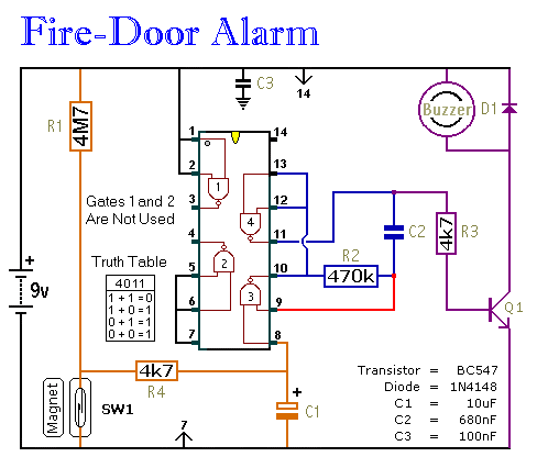
A Simple Fire-Door Alarm circuit

This circuit provides an alert when a door that should remain closed is left open. It is designed to be attached to a fire door, allowing normal passage. If the door remains open for more than 30 seconds, a buzzer will activate to signal the issue.
The circuit operates using a simple mechanism involving a door switch, a timer, and a buzzer. The door switch is typically a magnetic reed switch or a mechanical switch that closes when the door is in the closed position. When the door is opened, the switch is triggered to open, initiating the timing sequence.
A timer circuit, which can be implemented using a 555 timer IC in monostable mode, is used to monitor the duration the door remains open. The timer is configured to start counting when the door switch opens. If the door remains open for the preset duration of 30 seconds, the output of the timer goes high, activating the buzzer.
The buzzer can be a simple piezoelectric buzzer or a more complex sound-generating device, depending on the desired alert sound. The circuit can be powered by a standard DC power supply, and it is advisable to include a power indicator LED to show when the circuit is operational.
To enhance reliability, it is recommended to incorporate a debounce circuit for the door switch to prevent false triggering due to mechanical vibrations or noise. Additionally, the circuit can be designed with a reset button to allow manual resetting of the timer after the alert has been triggered.
Overall, this circuit serves as an effective safety measure for fire doors, ensuring that they remain closed when necessary to prevent the spread of fire and smoke.This circuit will let you know when something that should be kept closed - has in fact been left open. Attach it to a Fire-Door. It will allow you to pass through the door as usual. However, if it`s left open for more than 30-seconds or so - the buzzer will sound.. 🔗 External reference


