
RF amplifier circuit 1W 2.3GHz MRF2001

The RF amplifier circuit utilizing the MRF2001 transistor is designed to operate efficiently in the frequency range of 2.25GHz to 2.35GHz, making it suitable for various microwave communication applications. The MRF2001 is a high-performance RF power transistor that can deliver a power output of approximately 1 Watt, which is essential for achieving sufficient signal strength in communication systems.
The circuit is powered by a 24V supply voltage, which is critical for maintaining the performance characteristics of the amplifier. The minimum gain of 8 dB ensures that the input signal is amplified significantly, enhancing the overall system performance. The ability to tune the frequency within a narrow band allows for flexibility in different applications, enabling the circuit to adapt to specific communication requirements.
In practical applications, this amplifier can be integrated into microwave transmitters or receivers, where medium-power amplification is necessary. Its design may include additional components such as matching networks and biasing circuits to optimize performance and ensure stability across the specified frequency range. Proper thermal management should also be considered to prevent overheating during prolonged operation, which could affect the reliability and longevity of the amplifier.
Overall, the MRF2001-based RF amplifier circuit is a robust solution for medium-power amplification in microwave communication systems, providing essential features such as tunability, adequate gain, and power output to meet the demands of modern RF applications.RF amplifier circuit diagram, deliver 1W for 2. 3GHz, built based MRF2001. This RF amplifier delivers about 1 Watt power output with 8-dB minimum gain at 24V voltage supply. The frequency can be tuned from 2. 25GHz to 2. 35GHz. Applications include microwave communications equipment and other systems that require medium-power narrow-band amplificatio n. 🔗 External reference
Related Circuits
This circuit is designed for dimming devices powered by transformer-based power supplies, specifically those operating at 12, 24, or 48 volts, rather than standard 120 volts. The project involves various components, including a soldering iron, wire strippers, breadboard or...
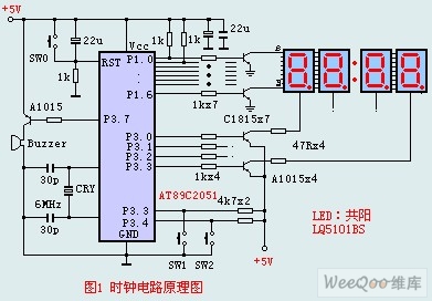
The circuit design incorporates an anodic Nixie tube for the LED display. It utilizes the LQ5101BS general luminous diode, with the driving transistor being either the 2SA1015 or 2SC1815 types, which are readily available. Additionally, low-power transistors such as...
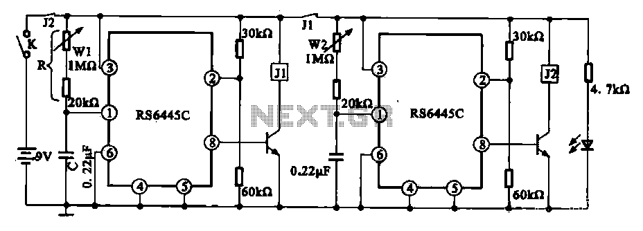
The timing integrated circuit (IC) RS6445C functions as a blocking oscillator. It features two segments, WI and W2, which are utilized to adjust the working time and the closure time. These adjustments can be continuously set within a range...
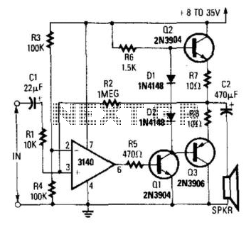
A CA3140 operational amplifier drives a complementary output stage consisting of transistors Q1, Q2, and Q3. The output power is influenced by the supply voltage and the thermal dissipation limits of transistors Q2 and Q3. Under optimal conditions, the...
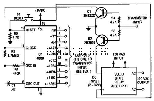
A long-duration timer can be easily constructed using a 4060 CMOS binary divider along with its integrated clock oscillator. The solid-state relay can be selected based on the specific application requirements and may be substituted with a mechanical relay...
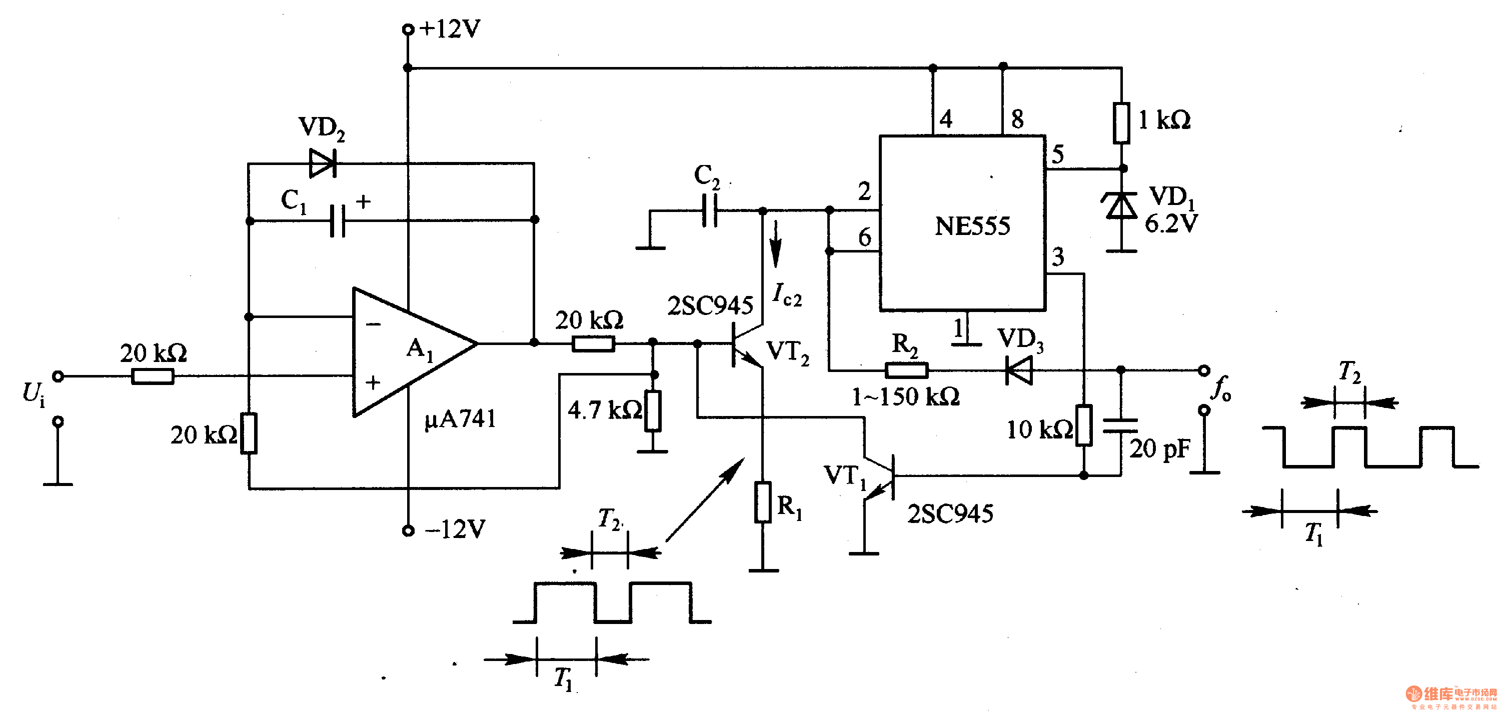
In the circuit, the oscillation frequency of the NE555 is controlled by VT2. When the output at pin 3 is low (during the T1 period), VT1 stops conducting, and VT2 begins to conduct with a current Ic2 flowing through...