
A Simple Keypad-Operated Switch - with enhanced security

The universal four-digit keypad-operated switch circuit is designed to enhance security through simultaneous code entry and a time-lock feature. The circuit utilizes a microcontroller or IC to process input from the keypad. The simultaneous pressing of four keys is detected by the microcontroller, which then verifies whether the input matches the stored security code. If the code is correct, the microcontroller will deactivate a relay, allowing connected devices to operate.
The time-lock feature is implemented using a combination of resistors and diodes to create a delay after incorrect attempts. The values of resistors R8 and R9 can be adjusted to modify the lockout duration, providing flexibility in how the security system responds to unauthorized access attempts.
In terms of hardware, the circuit requires careful layout considerations to ensure that low-voltage components are adequately isolated from high-voltage relay contacts. The choice of a relay should be based on the specific load requirements, and it should be mounted in a location that minimizes risk.
The keypad should be chosen based on the number of keys desired, with a recommendation for a matrix-type keypad that provides individual connections for each key. The circuit's design allows for scalability, enabling the use of larger keypads to increase the number of possible combinations and enhance security.
Overall, this keypad-operated switch circuit is a robust solution for applications requiring secure access control, with features that can be tailored to meet specific user needs while maintaining a high level of security.This is a universal four-digit keypad-operated switch - with a difference. Instead of entering the security code one number at a time - the four keypad buttons must be pressed simultaneously. In other words - the four numbers must be entered in parallel. The intruder won`t know the code. He won`t even know how many digits there are in the code. An d he almost certainly won`t know that the entire code must be entered simultaneously. Added to this - is the extra layer of security provided by the secret time-lock. After a few incorrect codes are entered - the circuit will stop responding to the keypad. And any further attempts to crack the code - will be unsuccessful. If you don`t want the time-lock feature - leave out D6, C6, R8 & R9. And connect pins 8 & 9 of the IC together. If you want to use a three-digit security code - leave out D4, C4 & R4. And connect pins 5 & 6 of the IC together. Three digits are easier to enter than four. Do not use the "on-board" relay to switch mains voltage. The board`s layout does not offer sufficient isolation between the relay contacts and the low-voltage components. If you want to switch mains voltage - mount a suitably rated relay - somewhere safe - Away From The Board.
Choose the four keys you want to use for your code - and connect them to "A B C & D". Since the keys have to be pressed simultaneously - the order in which you make the connections is irrelevant. Wire the keypad`s common terminal to "Com". And connect all the remaining keys to ground. That is - to "E". The circuit will power-up with the relay energized. When you press keys "A B C & D" simultaneously - the relay will de-energize. To energize it again - press any key not included in your code. That is - any key connected to "E". If you want to reverse the action of the circuit - replace the PNP transistor - with an NPN transistor.
If you use a BC547 instead of a BC557 - the circuit will power-up with the relay de-energized. And it will energize when you enter your code. If you make more than a couple of attempts to enter an incorrect code - the circuit will lock you out. How quickly it does so - depends on the value of R8. If you are locked out - you must wait for a minute or so - before you enter the correct code. How long you have to wait - depends mainly on the value of R9. If you don`t wait long enough - and you keep trying to enter incorrect codes - the circuit will keep you locked out.
The total number of different codes - or key patterns - available depends on the number of keys in your pad. With a 12-key pad - there`s a choice of 495 different groups of four keys. If you want a more secure code - use a bigger keypad. A 16-key pad lets you choose from 1820 different groups of four. You can also split the code between two separate keypads. If you mount the keypads far enough apart - two people will have to be present in order to operate the switch.
And by using the technique described on the Support Page - under the heading - General Information - each person can have his own unique three-digit security code. The keypad itself must be the kind with a common terminal - and a separate connection for each key. On a 12-key pad - look for 13 terminals. The matrix type with 7 or 8 terminals will NOT do. The Support Material for this circuit includes details of how to make a suitable keypad. It also includes a detailed circuit description - a parts list - a step-by-step guide to the construction of the circuit board - and more.
🔗 External reference
Related Circuits
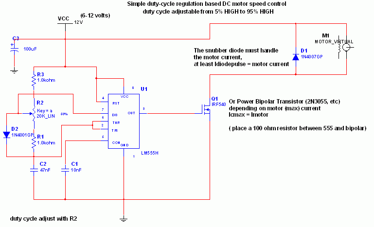
The 555 IC is configured in an astable mode, producing a frequency that remains constant and is independent of the duty cycle. The total resistance (Rcharge + Rdischarge, considering the diode) is fixed at 22 kΩ, yielding a frequency...
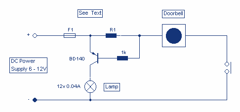
This circuit will light a lamp at a remote location when the doorbell switch is pressed. This circuit should only be used with the solenoid type doorbells; the electronic type that play tunes will not work here. It is...
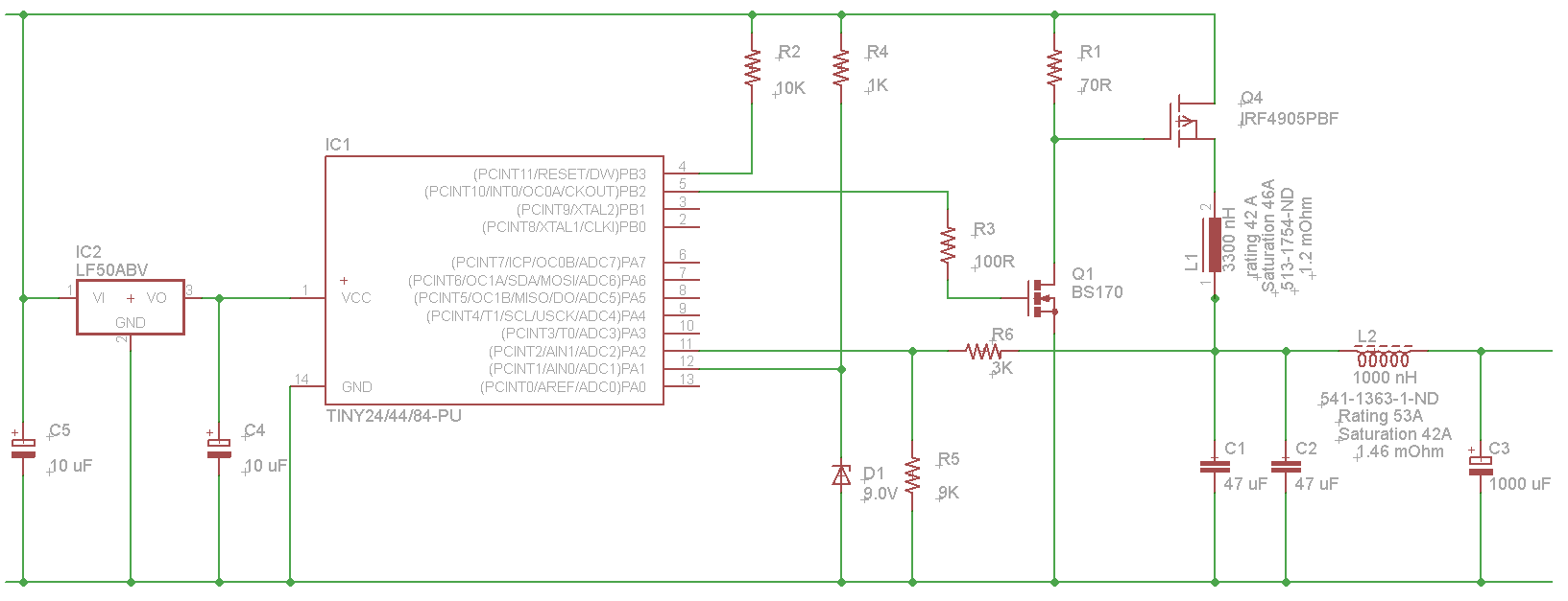
The microcontroller will not be able to drive the gate of Q1 effectively, as GPIO pins typically can only source a few milliamps, resulting in slow turn-on and turn-off times. This limitation will affect the performance of the high-side...

A simple lab power supply electronic project can be designed using this circuit diagram, which is based on the LM2576 monolithic integrated regulator that provides all the active functions for a step-down (buck) switching regulator. As seen in the...
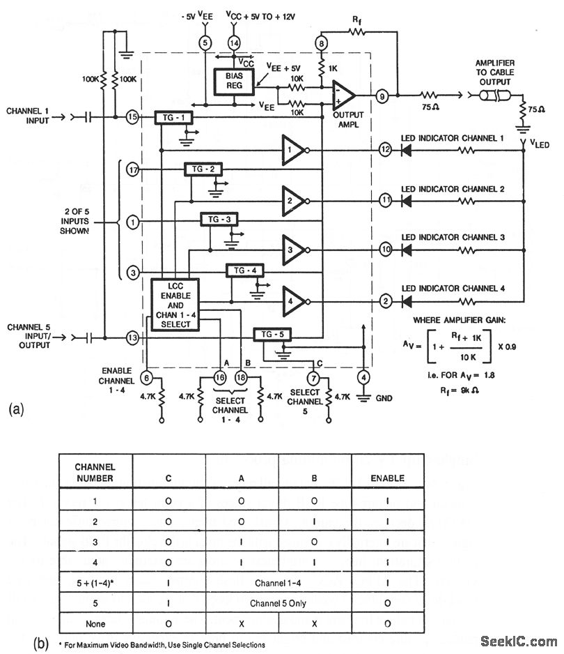
This circuit illustrates a CA3256 switch/amplifier configured for a direct-coupled output. One of four channels can be selected in parallel with channel 5. The analog switches of channels 1 to 4 are digitally controlled by logic. A VEE of...
12 Volt / 2 A Switching Power Supply. Refer to the corresponding page for an explanation regarding the circuit diagram related to the above power supply. The 12 Volt / 2 A Switching Power Supply is designed to convert a...