
12 volt 2 a switching power supply

The 12 Volt / 2 A Switching Power Supply is designed to convert a higher input voltage into a stable 12 V output with a maximum current of 2 A. This type of power supply utilizes a switching regulator to achieve high efficiency and compact size. The primary components of the circuit typically include a transformer, rectifier, filter capacitors, and a control circuit.
The operation begins with the input AC voltage being transformed down to a lower AC voltage by the transformer. The output from the transformer is then rectified using a bridge rectifier configuration, which converts the AC voltage to DC. The rectified voltage is smoothed out by filter capacitors to reduce ripple, providing a more stable DC voltage.
The switching regulator, often based on integrated circuits (ICs) such as the LM2596 or similar, is responsible for maintaining the output voltage at 12 V. It does this by rapidly switching the input voltage on and off, controlling the average voltage delivered to the load. Feedback mechanisms are implemented to monitor the output voltage and adjust the duty cycle of the switching to ensure consistent output under varying load conditions.
Protection features may include over-voltage protection, over-current protection, and thermal shutdown to prevent damage to the power supply and connected devices. The design can be further enhanced with additional components such as inductors for filtering and improving transient response.
Overall, the 12 Volt / 2 A Switching Power Supply is a versatile and efficient solution for powering various electronic devices, making it a common choice in consumer electronics, industrial applications, and DIY projects.12 Volt / 2 A Switching Power Supply power supply. Go to that page to read the explanation about above power supply related circuit diagram. 🔗 External reference
Related Circuits
This document discusses the advantages and disadvantages of various power supply technologies, along with the design considerations necessary for selecting and evaluating a mains transformer. It covers the pros and cons of external supplies, inrush current control, RF emissions...
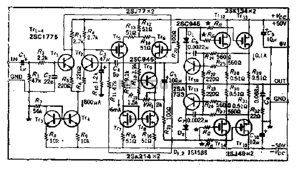
The circuit consists of three identical basic stages, with the second stage featuring a differential output from the power MOSFET, 2SJ77. A current mirror circuit utilizing 2SK214 is implemented. The operating current is 6mA; however, due to the power...
Portable radios, CD players, and cassette recorders that can also be operated from mains power often do not have a mains power switch, but instead are switched on and off using a different mechanism. Portable audio devices such as radios,...
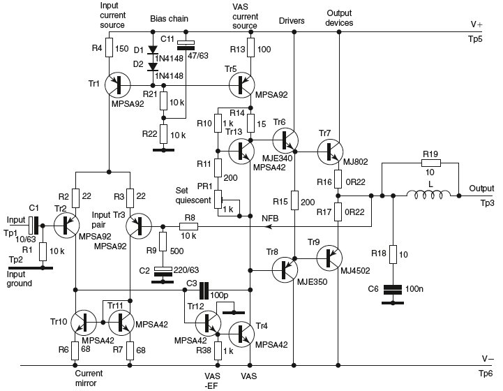
Most devices used in amplifier output stages exhibit significant non-linearity, with transistors (both bipolar and FET) being particularly problematic. These components are almost always employed within a global feedback loop to mitigate their non-linear characteristics. Similarly, tetrode and pentode...
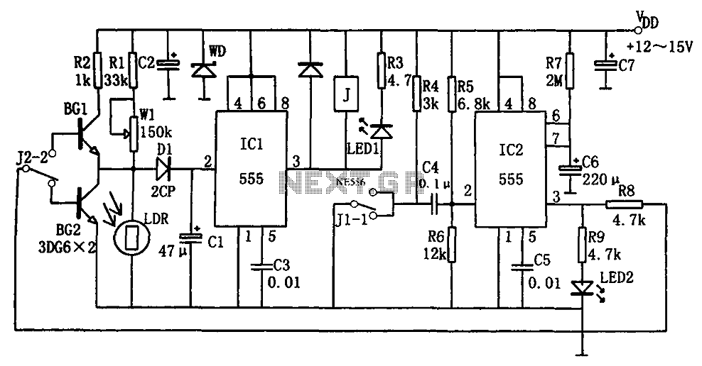
The optical control circuitry for high-performance street lighting is depicted in the figure. The circuit comprises a photoelectric conversion element, specifically a Light Dependent Resistor (LDR), a comparator circuit using an integrated circuit (IC1) which is a 555 timer,...
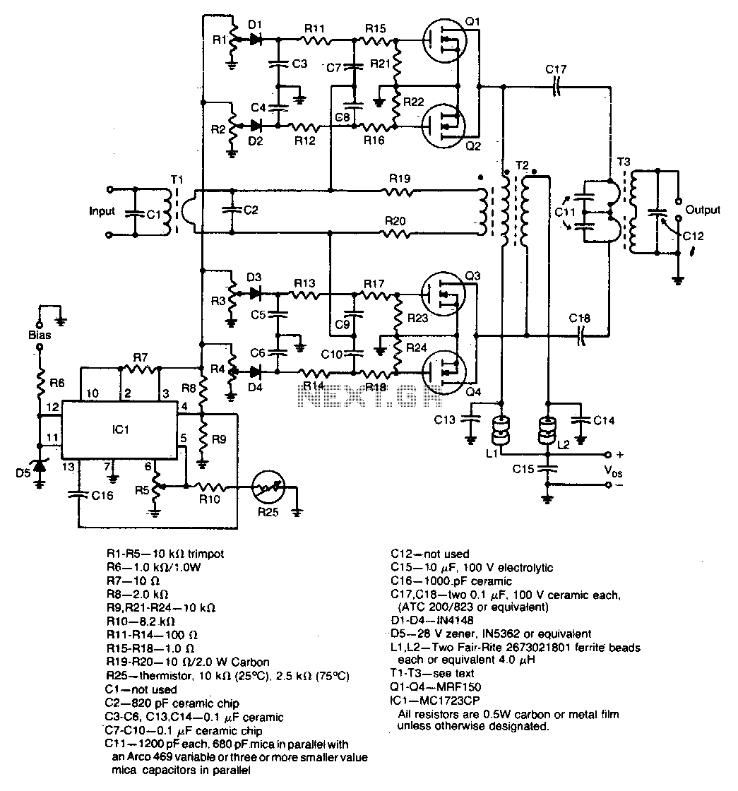
A unique push-pull parallel circuit utilizes four MRF150 RF power FETs connected in parallel at relatively high power levels. Supply voltages ranging from 40 to 50 Vdc can be employed, contingent on the linearity requirements. The bias for each...