
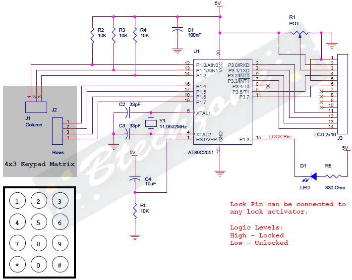
Combination Lock Circuit

The described circuit functions as a sequential lock mechanism, utilizing a series of momentary push-button switches (S1, S2, S3, S4) to control a load (K1). The operational principle is based on the requirement to press the switches in a specific order to activate the lock.
The circuit can be constructed using a microcontroller or a simple logic circuit with flip-flops to track the correct sequence of inputs. Each momentary switch is connected to an input pin of the microcontroller or to the clock input of a flip-flop. When a switch is pressed, it sends a signal to the circuit, which checks if the input corresponds to the next expected switch in the sequence.
If the correct switch is pressed, the circuit proceeds to the next switch in the sequence. If an incorrect switch is pressed, the circuit resets, requiring the user to start over. This feature can be implemented using a reset mechanism, which can be a simple logic gate configuration or a software routine in a microcontroller.
The wiring of the switches can be arranged in various configurations, allowing for flexibility in the choice of switch combinations. For instance, the switches can be connected in parallel to a common input line, with each switch having a unique identifier in the software or logic circuit.
The load (K1), which could be a solenoid, relay, or any other actuating device, is activated once the complete sequence is successfully entered. To ensure user feedback, the circuit may incorporate LEDs or buzzers to indicate the status of the input sequence, providing visual or auditory cues for correct or incorrect inputs.
Overall, this circuit is a straightforward yet effective implementation of a sequential locking mechanism, suitable for various applications requiring controlled access.This circuit is very basic to build. To open a the lock which is connected to the K1 Load you must press each momentary switch in the correct sequence. The sequence used in this circuit is S1,S2,S3,S4. If any of the other switches are pressed the circuit will reset and you will need to start over. Depending on how you wire the switches, you can use any 4 switch combination. 🔗 External reference
Related Circuits
The entire series of TTL monostable multivibrators lacks sufficient speed, prompting the need for an ECL voltage swing that accommodates a wide range of small power requirements. This necessitates the use of F series circuits, which offer fast transition...
Warning: Missing argument 2 for wpdb::prepare(), called in /home3/nithish/public_html/btechzone.com/wp-content/plugins/sharebar/sharebar.php on line 112 and defined in /home3/nithish/public_html/btechzone.com/wp-includes/wp-db.php on line 992 Warning: Missing argument 2 for wpdb::prepare(), called in /home3/nithish/public_html/btechzone.com/wp-content/plugins/sharebar/sharebar.php on line 124 and defined in /home3/nithish/public_html/btechzone.com/wp-includes/wp-db.php on line 992 This...
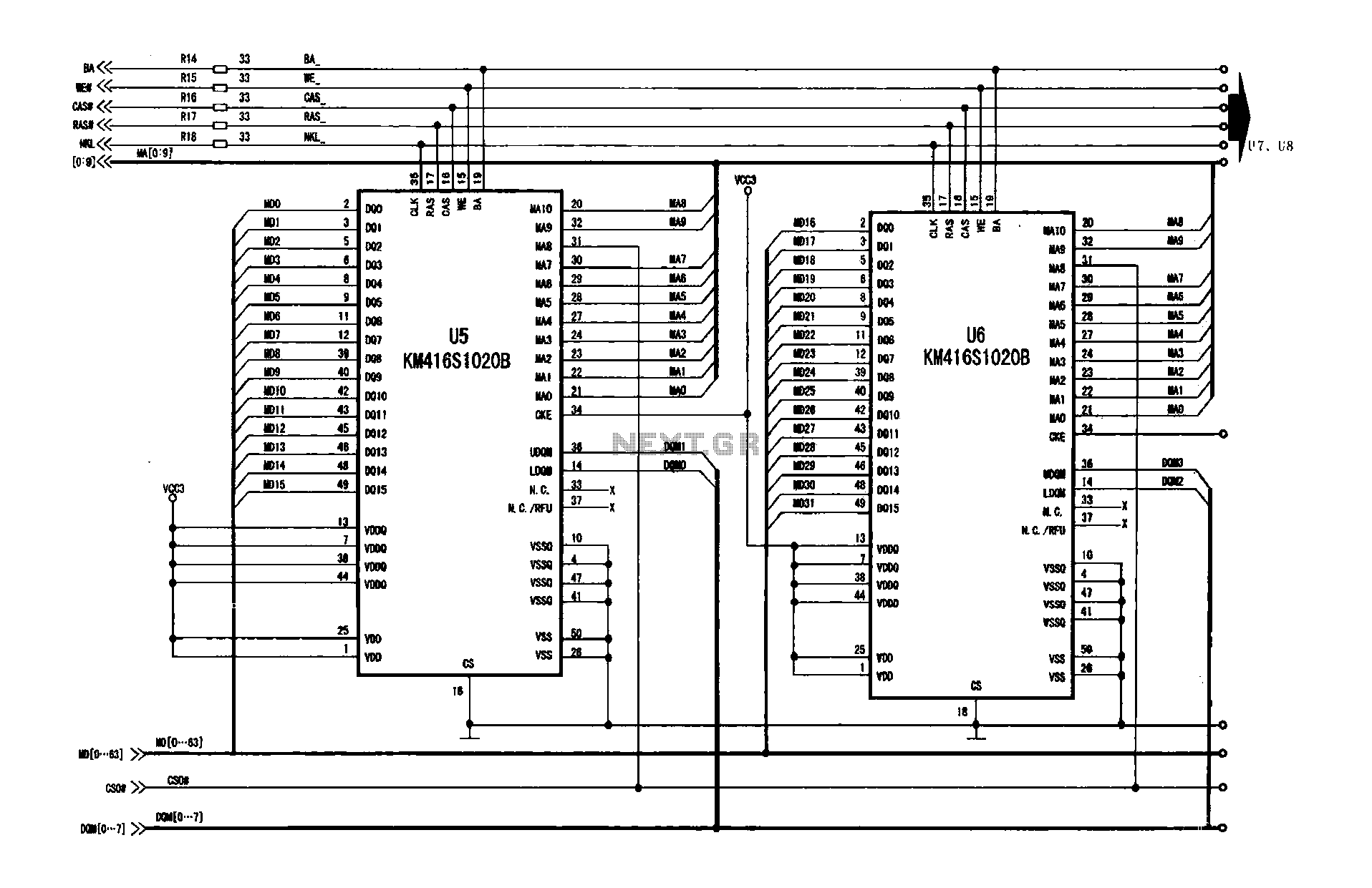
A digital signal processing circuit that operates in conjunction with a memory system for temporarily storing image data. The DPTVT-3D/MV digital processing chip requires four KM416S102 memory units, each providing 16 MB of digital memory. The circuit structure is...
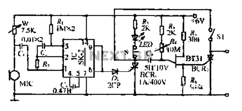
The circuit includes a microphone (MIC) housed in a cylindrical body that captures sound when an object makes contact. The audio signal is coupled to an integrated circuit (IC) for amplification. The output from the IC, at pins 6...
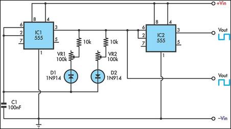
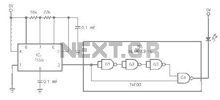
This timer utilizes two 555 integrated circuits (ICs) to adjust the desired output. The variable resistors VR1 and VR2 serve as potentiometers to modify the cycle speed. The circuit can be powered with a 9 to 12-volt power supply,...
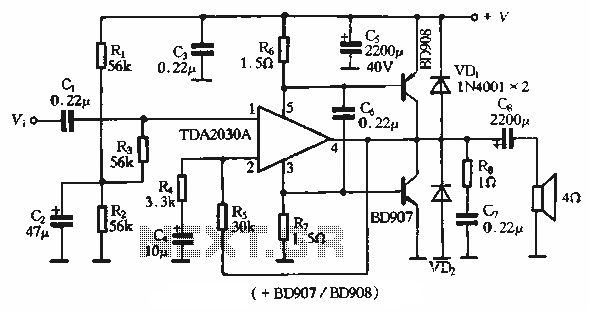
The rDA2030A TDA2030 is an enhanced version of the original product, with a maximum working voltage increased to 18V and a maximum output power of 18W. Additionally, harmonic distortion has been significantly reduced. The application circuit is illustrated. The rDA2030A...