
a simple variable power supply circuit

This variable power supply circuit utilizes the L200 integrated circuit, which is designed for adjustable voltage regulation. The L200 can provide a stable output voltage that can be finely tuned using a 10K potentiometer, allowing for a versatile range of applications. The output voltage can be adjusted between approximately 3V and 15V, making it suitable for powering various electronic devices that require different voltage levels.
The circuit operates by connecting the L200's output to the load, with the voltage adjustment achieved through the variable resistor. The potentiometer alters the feedback voltage to the L200, effectively changing the output voltage according to the user's requirements. The current output capability of the circuit ranges from a minimum of 10 mA to a maximum of 2 A, ensuring that it can handle a variety of loads without overheating or becoming unstable.
In terms of design, it is important to include appropriate filtering capacitors on both the input and output sides of the L200 to ensure stable operation and minimize voltage ripple. Additionally, heat dissipation should be considered, as the L200 can generate heat under load. A suitable heat sink may be required to maintain safe operating temperatures.
This variable power supply circuit is ideal for laboratory use, prototyping, and other applications where adjustable voltage and current are necessary. The simplicity of the design, combined with the flexibility of the L200 IC, makes it a valuable tool for engineers and hobbyists alike.Variable power supply based L200 for its output voltage is controlled by a variable resistor 10K. Output voltage range of values is from around 3 to 15 volts, and current range is about 10 mA minimum and a maximum of 2 amps. The schematic diagram come from circuit: A simple variable power supply circuit with L200 power supply.
Go to that page toread the explanation about above power supply related circuit diagram. 🔗 External reference
Related Circuits
This is a fun and non-dangerous project for those people who like to throw projectiles magnetically. It simply works by placing a ferromagnetic projectile at one end of a coil and pulsing some power in it. The trick is...
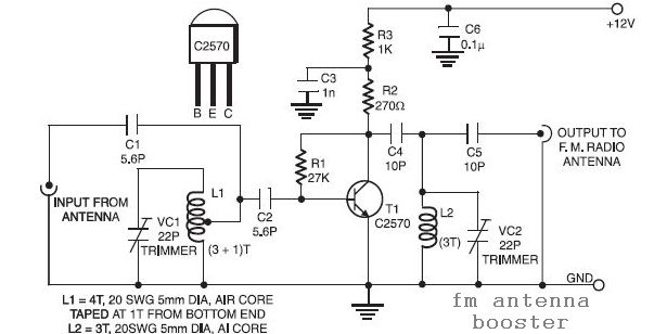
This is a low-cost FM antenna booster that can be used to listen to programs from distant FM stations clearly. The antenna FM booster circuit comprises a... The FM antenna booster circuit is designed to enhance the reception of FM...
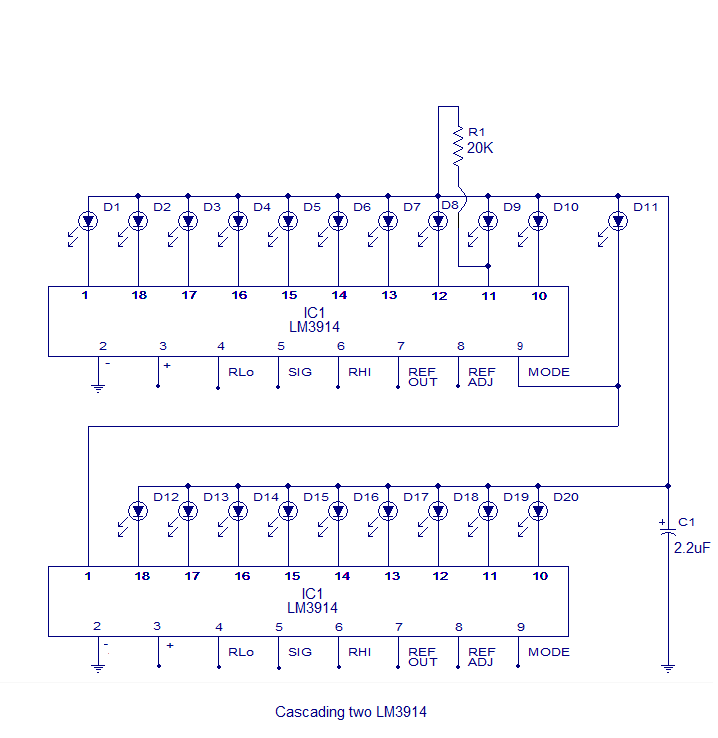
The core of this circuit is the LM3914 from National Semiconductor. The LM3914 is capable of sensing voltage levels and can drive a display of 10 LEDs in either dot mode or bar mode. The selection between bar mode...

FAN7710 Ballast Control circuit design for Compact Fluorescent Lamps electronic project. The FAN7710 is a specialized integrated circuit designed for the control of ballast systems in compact fluorescent lamps (CFLs). This circuit typically operates in a high-frequency range, facilitating efficient...
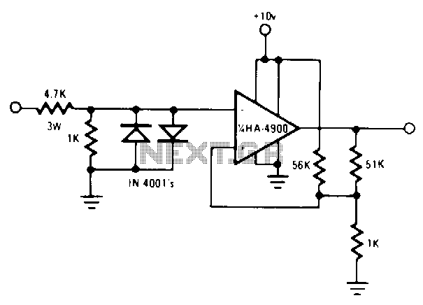
Utilize a pair of Maxim's 5V-powered MAX231 RS-232C transmitters as drivers to achieve a dual-color LED. These transmitters necessitate only a single-ended, 5-V input to internally generate ±10 V. Their outputs are designed to be short-circuit-proof and can provide...
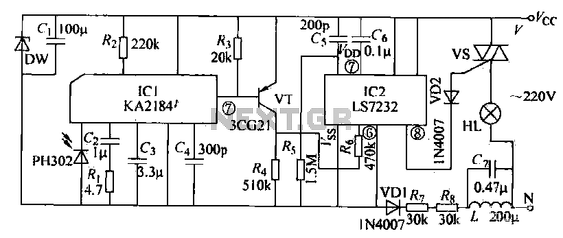
The receiving circuit operates as follows: when the infrared receiver detects a signal from the remote control transmitter, the KA2184 processes this signal, resulting in a low output at the pin. This low output is directly connected to the...