
FAN7710 Ballast Control circuit design

The FAN7710 is a specialized integrated circuit designed for the control of ballast systems in compact fluorescent lamps (CFLs). This circuit typically operates in a high-frequency range, facilitating efficient energy conversion and regulation necessary for the optimal functioning of CFLs. The FAN7710 incorporates various features aimed at enhancing the performance and reliability of the ballast control system.
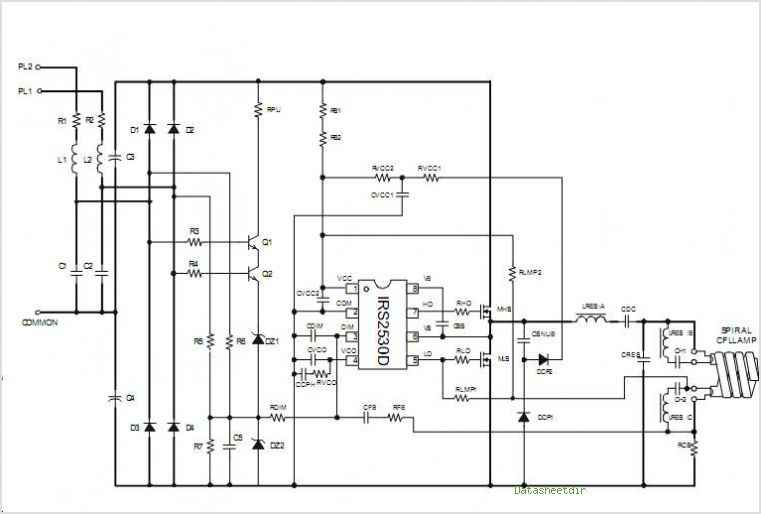
The circuit design generally includes essential components such as inductors, capacitors, and resistors, which work in conjunction with the FAN7710 to create a stable operating environment for the lamp. The integration of feedback mechanisms is crucial for maintaining the desired output voltage and current, ensuring that the CFL operates within its specified parameters.
Furthermore, the FAN7710 supports features such as soft-start capabilities, which help to reduce inrush current during lamp ignition, thereby prolonging the lifespan of the CFL. The circuit may also incorporate protection mechanisms against over-voltage, over-current, and thermal overload conditions, enhancing overall safety and efficiency.
In terms of layout, careful attention must be paid to the placement of components to minimize electromagnetic interference (EMI) and optimize thermal management. Proper grounding and decoupling strategies are essential to ensure the stability of the circuit during operation.
Overall, the FAN7710 ballast control circuit design for compact fluorescent lamps represents a sophisticated approach to energy-efficient lighting solutions, combining advanced control techniques with robust protection features to deliver reliable performance in various applications.FAN7710 Ballast Control circuit design for Compact Fluorescent Lamps electronic project. 🔗 External reference
Related Circuits
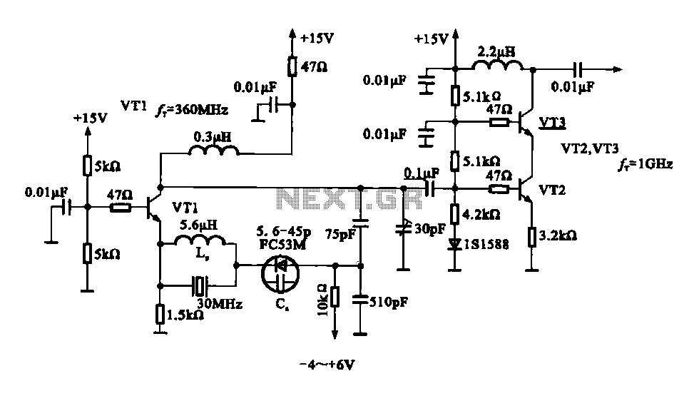
A variable frequency oscillator transistor circuit, primarily functioning as an oscillator, incorporates a crystal resonator and a varactor diode. The output is amplified, typically used for generating high-frequency signals. This 30 MHz transistor circuit features an inductor (LP) connected...
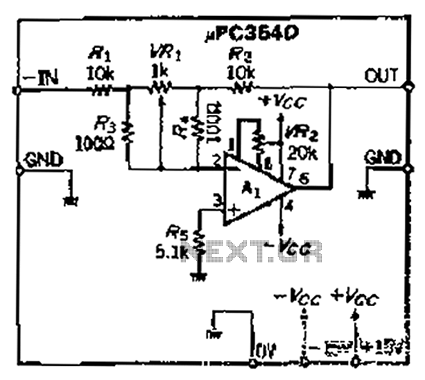
The loop gain of the operational amplifier (OP) is primarily influenced by the ratio of the input resistor to the feedback resistor. Consequently, any resistance error can lead to a corresponding gain error, which necessitates the use of high-precision...

This is a circuit known as a Wien bridge oscillator circuit. The circuit features both positive and negative feedback loops and operates under the control of an operational amplifier (op-amp). The oscillation frequency is determined by the RC time...
A phase-locked loop (PLL) is widely utilized in telecommunications, control systems, and various other electronic applications. PLLs can be employed to demodulate frequency-modulated (FM) signals and generate a stable output frequency. A phase-locked loop is an essential feedback control system...
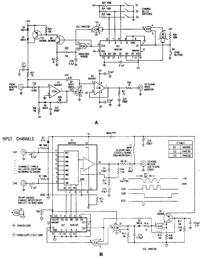
In the video system shown in Figs. A and R, a single coaxial cable transmits power to a remote location, selects one of eight video channels, and returns the chosen signal. This system can select from multiple remote surveillance...
Generating and manipulating sine wave functions is a common challenge faced by circuit designers. Sine wave circuits present significant design difficulties because they function as continuously controlled linear oscillators. Such circuitry is essential in various fields, including audio testing,...