
FM Antenna Booster Circuit

The FM antenna booster circuit is designed to enhance the reception of FM radio signals, particularly from distant stations. This circuit typically includes a few essential components: an operational amplifier (op-amp), a matching network, and a power supply.
The operational amplifier serves as the core of the circuit, amplifying the weak signals received by the antenna. The input stage of the op-amp is configured to optimize the signal-to-noise ratio, ensuring that the desired FM signals are amplified without introducing significant noise.
The matching network, which may consist of inductors and capacitors, is crucial for impedance matching between the antenna and the op-amp. This network helps to maximize power transfer and minimize signal reflection, thereby improving overall reception quality.
Power supply requirements for the circuit can vary, but it is generally designed to operate with low voltage DC sources, making it suitable for battery operation or connection to wall adapters.
In practical applications, the FM antenna booster can be connected directly to an existing FM antenna or can be used with a dedicated antenna designed for enhanced performance. By improving the signal strength and clarity of the received FM broadcasts, this circuit allows users to enjoy a broader range of stations and improved audio quality.
Overall, the low-cost FM antenna booster circuit is an effective solution for enhancing FM radio reception, particularly in areas where signal strength is weak or obstructed.This is a low cost fm antenna booster that can be used to listen to programmes from distant FM stations clearly. The antenna fm booster circuit comprises a.. 🔗 External reference
Related Circuits
Many amplifiers have phono inputs for connecting record players to the amplifier. Phono input is designed to take a up to few millivolt signal from phono pickup and amplify it. The amplifier stage does also some equalization based on...
The metal detector circuit is shown here that the limits represent the sake of simplicity for a metal detector, but the design works remarkably well. It only uses 40,106 Hex Schmitt inverter IC, a capacitor and a search coil...
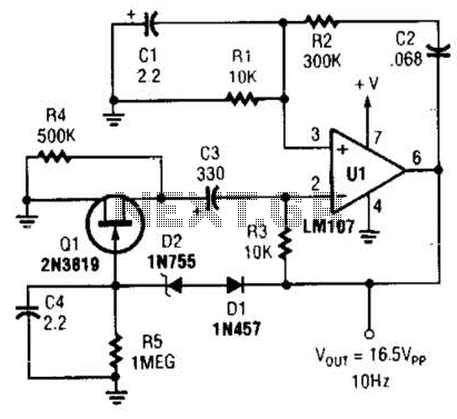
This Wien-bridge sine-wave oscillator utilizes a 2N3819 as an amplitude stabilizer. The 2N3819 functions as a variable-resistance element within the Wien bridge. The Wien-bridge oscillator is a type of electronic oscillator that generates sine waves. It employs a bridge circuit...
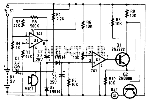
In the circuit, U1 amplifies the audio captured by the condenser microphone. Resistor R1 limits the current, while R2 and R3 center the amplifier's output to a voltage level of %B+ to facilitate the use of a single-ended power...
This circuit provides a visual 9-second delay using 10 LEDs before closing a 12-volt relay. When the switch is closed, the 4017 decade counter will reset to zero, illuminating the LED connected to pin 3. The output at pin...

A straightforward smoke detector circuit has been presented through a schematic diagram, which can be easily constructed and installed in an area for essential detection purposes. The circuit utilizes the versatile FIGARO TGS 813 gas sensor as the primary...