
A simplified circuit diagram of an electronic ballast

The described circuit employs a resonant converter configuration for driving fluorescent lamps efficiently. The operation begins with the alternating activation of two switches, S1 and S2, which creates a high-frequency rectangular wave. This frequency range, typically between 25 kHz and 100 kHz, is chosen to optimize the performance of the fluorescent lamp while minimizing energy losses.
The resonant circuit comprises an inductor and a capacitor, forming a resonant tank circuit. The capacitor is strategically placed to filter out any DC components that could affect the lamp's performance. By ensuring that only the AC component is delivered to the load, the circuit maintains a stable and efficient operation.
The resonant capacitor, denoted as C, plays a critical role in establishing the necessary voltage across the lamp to initiate the arc discharge. When the voltage reaches a certain threshold, the gas inside the fluorescent tube ionizes, allowing current to flow and the lamp to illuminate. The high-frequency excitation not only facilitates the initial arc strike but also keeps the lamp in a continuous conductive state, which is essential for achieving a flicker-free lighting effect.
This design is particularly advantageous in building applications where energy efficiency is a priority. By employing dimmable electronic ballasts, facilities can adjust the light output according to specific needs, thereby achieving significant energy savings. The combination of resonant conversion technology and dimmable capabilities makes this approach a modern solution for effective fluorescent lighting in various architectural environments.Construction of buildings, when full power is not required fluorescent continuous operation, the application dimmable electronic ballasts can further reduce power consumption w ithin buildings to achieve energy savings. Most modern electronic ballast design and research, are recommended as driving the lamp resonant converter power circuits. Figure 1 shows a simplified circuit of the ballast. Two switches S: and S2 are switched alternatively, to provide a high frequency (typically less than 25 kHz and 100 kHz) of the rectangular wave AC voltage is applied to the load resonant circuit.
Separated (broken) straight (stream) capacitor used to eliminate the DC voltage component. The basic concept is to utilize the resonant capacitor C, the voltage on the resonance, in order to stimulate the lamp arc to strike. Because of the high frequency excitation voltage, the lamp is essentially in a continuous conductive state, it can provide high-quality, flicker-free lighting effect.
Related Circuits

The digital circuit that is particularly useful is the One-Shot circuit, also known as a monostable multivibrator circuit. This circuit exhibits a specific behavior where it generates a single output pulse in response to an input trigger. The One-Shot circuit,...
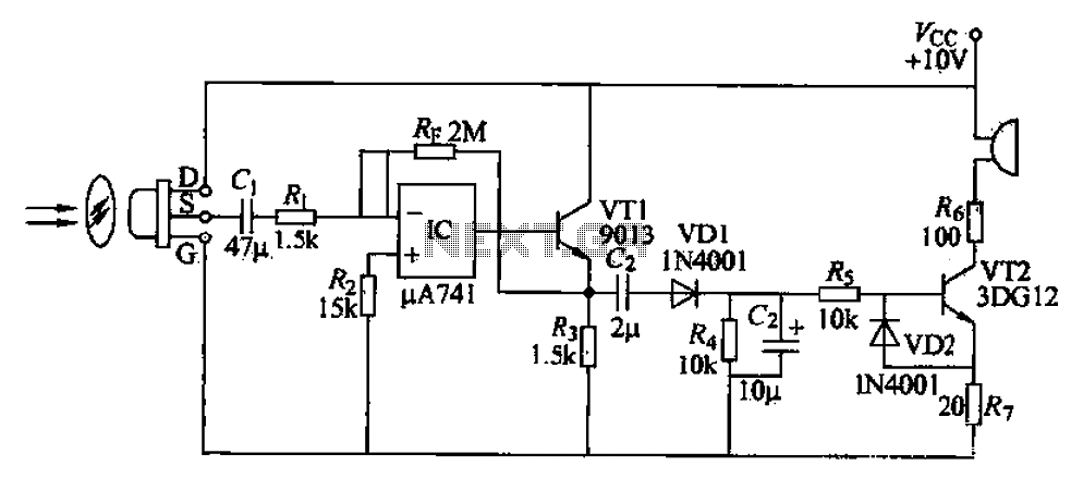
A simple burglar alarm circuit utilizes a pyroelectric sensor (IRA-E100SZI). When human movement is detected, it triggers an electric buzzer alarm. The sensor receives signals through an AC amplifier, which is then converted by a rectifier circuit into a...
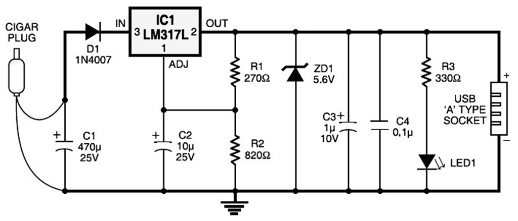
A USB port is capable of supplying more than 100 mA of continuous electric current at 5V to peripherals connected to the bus. This feature allows a USB port to power 5V DC-operated small electronic devices without issues. Many...
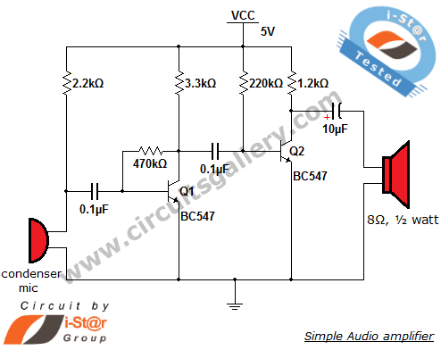
The output of the condenser microphone is coupled through a 0.1 µF coupling capacitor, which serves to eliminate DC components from the audio signal. Transistor Q1 is configured in a collector-to-base biasing mode, achieved with a 470kΩ resistor. This...
This circuit is designed for alerting purposes after a specified duration has elapsed. It is suitable for table games that require a fixed time limit to answer a question or to move a piece, serving as a modern substitute...
The delay-saving lamp circuit functions as a sound and light control delay energy-saving lighting system. It can directly replace a standard light switch without modifying the existing lighting circuits. In bright or daytime conditions, the sound control feature ensures...