
A six thyristor AC switch circuits

The six thyristor three-phase AC switching circuit is designed to control the power supplied to inductive loads such as motors. This circuit utilizes six thyristors arranged in a bridge configuration, allowing for precise control of the AC waveform supplied to the load. Each thyristor can be triggered at specific points in the AC cycle, enabling phase control of the power delivered to the load. This method is particularly effective for applications requiring variable speed control or soft starting of motors.
In contrast, the triac circuit configuration shown in Figure 16-48 (b) employs three triacs, which are semiconductor devices capable of conducting current in both directions when triggered. This setup simplifies the control of AC power to inductive loads by allowing for bidirectional current flow, making it suitable for applications where the load may reverse direction, such as in certain motor control scenarios.
Both configurations are essential for managing the power requirements of inductive loads, providing flexibility in operation. The thyristor circuit is typically favored for heavy-duty applications due to its robustness and ability to handle higher currents, while the triac circuit is often used in lighter applications due to its ease of use and lower cost. Proper heat management and protection circuitry should be implemented in both designs to ensure reliability and longevity of the components.Figure 16-48 (a) for the introduction of six thyristor three-phase AC switching circuit; Figure 16-48 (b) as adopted by three triac circuits. Suitable for motors and other indu ctive loads.
Related Circuits
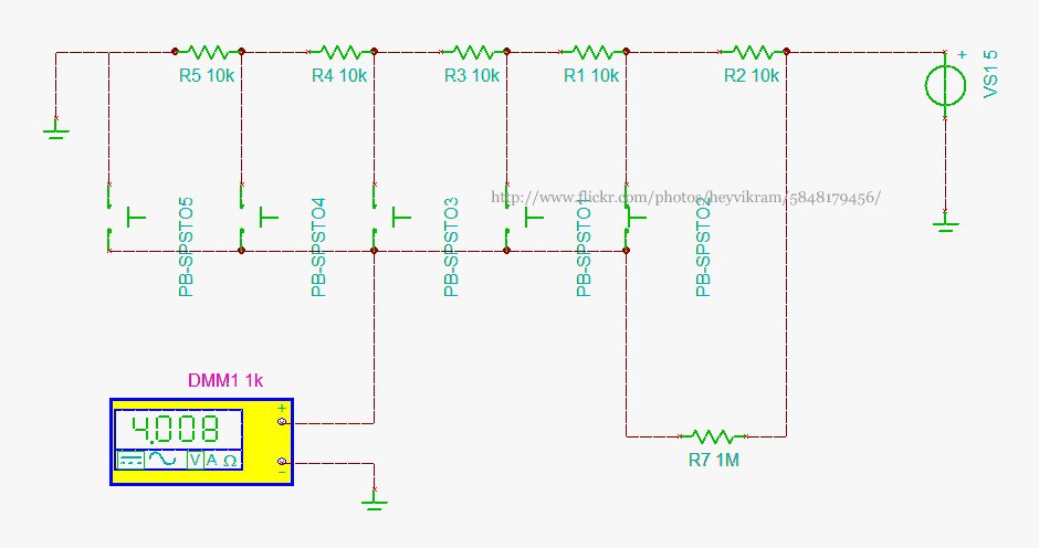
Connect a 5-way button/joystick to an Arduino using a single analog pin to quickly simulate it for verification of calculations before soldering. The voltages for the six states are 0, 1, 2, 3, 4, and 5. The 4V displayed...
This is a simple mains power failure alarm circuit that activates an alarm when the mains supply is lost. Unlike many similar circuits, this design does not require a backup power source, such as a battery, to operate the...
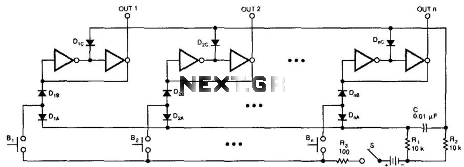
This switching circuit functions as a bank of interlocked mechanical switches. Activating one of the buttons latches its corresponding output while unlatching a previously selected output. A pair of inverters creates a latch for each output. For instance, pressing...
This sensitive sound-operated switch can be used with a dynamic microphone insert or with an electret (ECM) microphone. If an ECM is used, then R1 (shown dotted) will need to be included, with a suitable value between 2.2k and...

This halogen switch circuit utilizes a FET transistor, as the current is influenced by the gate voltage of the FET. The maximum gate voltage is 12V, making the circuit suitable for 12-volt lamps. The resistor R1 has a value...
This application note explains how the transfer function of most operational amplifier circuits can be derived through a straightforward process of nodal analysis. The transfer function of operational amplifier (op amp) circuits is a critical aspect for understanding their behavior...