
Halogen Light Switch Circuit

This halogen switch circuit is designed for efficient control of 12V halogen lamps using field-effect transistors (FETs). The FET operates as a switch, regulating the current flow based on the voltage applied to its gate. With a maximum gate voltage of 12V, the circuit is optimized for use with standard 12V halogen lighting systems, making it a practical choice for various applications, including home lighting and automotive uses.
The resistor R1 plays a crucial role in determining the gate voltage. The choice of resistor value—100 kΩ for 6V and 470 kΩ for 12V—allows for flexibility in operation, enabling the circuit to function correctly across different voltage levels. This adaptability ensures that the FET can effectively switch on and off, controlling the lamp's brightness and power consumption.
The circuit can utilize either the BUZ10 or BUZ11 FETs, both of which are capable of handling significant current loads. The BUZ10 can support up to 20A, while the BUZ11 can manage up to 30A, providing ample capacity for most halogen lamps. The choice between these two FETs will depend on the specific current requirements of the application, ensuring reliability and performance.
An important aspect of this circuit is the thermal management of the FETs. The design does not require a heatsink, as the FETs typically reach a maximum temperature of only 17 °C during operation. This characteristic simplifies the design and installation process, reducing the overall size and complexity of the circuit while maintaining safe operating temperatures.
Overall, this halogen switch circuit represents a straightforward yet effective solution for controlling 12V halogen lamps, leveraging the advantages of FET technology to achieve reliable performance and ease of use.In this halogen switch circuit we use a FET transistor because the current is dependent of the FET`s gate voltage. The maximum gate voltage is 12V, so this circuit is adequate for 12 volt lamps. R1 value is 100 k © for 6V and 470 k © for 12V. You can use BUZ10 which can outstand up to 20A or BUZ11 with maximum 30A. You don`t need heatsink for this FETs because they tend to warm up to only 17 °C. 🔗 External reference
Related Circuits
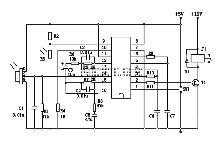
The BISS0001 is a high-performance integrated circuit designed for sensor signal processing. When combined with pyroelectric infrared sensors and a minimal number of external components, it forms a passive pyroelectric infrared switch. This device can automatically and quickly activate...
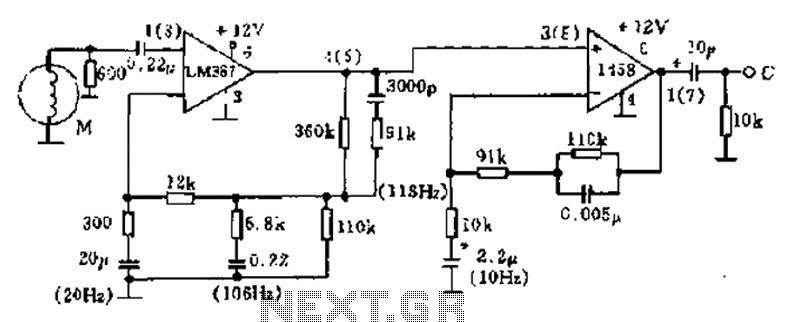
The phonograph pickup head is represented in the schematic as component M, which generates the pick-up signal and is processed through an LM387 amplifier circuit. The LM387 is part of the LM38X series, recognized for its advanced linear amplifier...
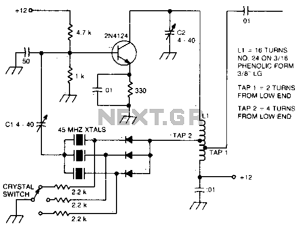
The large inductive phase shift of LI is compensated for by Cl. Overtone crystals have very narrow bandwidth; therefore, the trimmer has a smaller effect than for fundamental-mode operation. The statement discusses the compensation of inductive phase shifts in a...
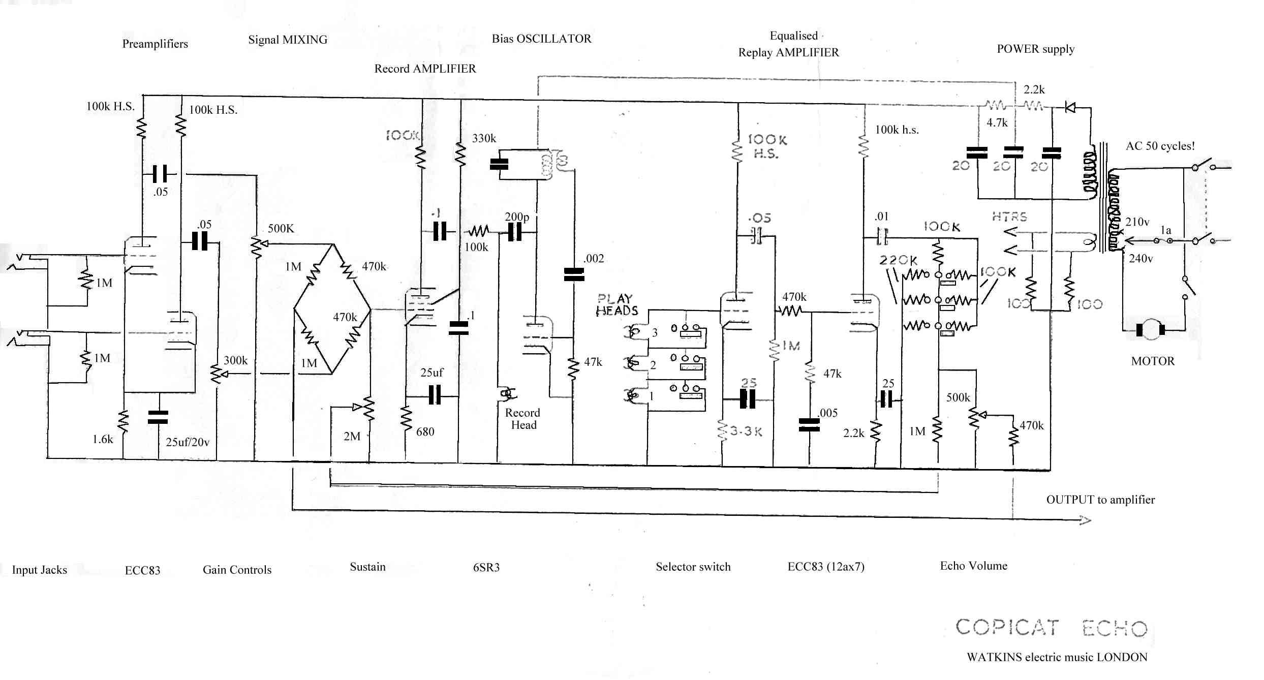
This is a request for assistance in designing a circuit for a tape delay unit. The mechanical components are functioning well, but the circuit integration remains a challenge. The tape heads used are cassette tape heads with a resistance...
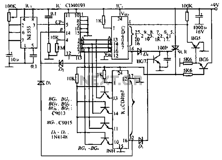
The circuit consists of an oscillator, a counter, and an Iseki circuit divided into three parts. The oscillator is based on the NE555 timer and several external RC components, generating a pulse signal for the counter. The instantaneous power...
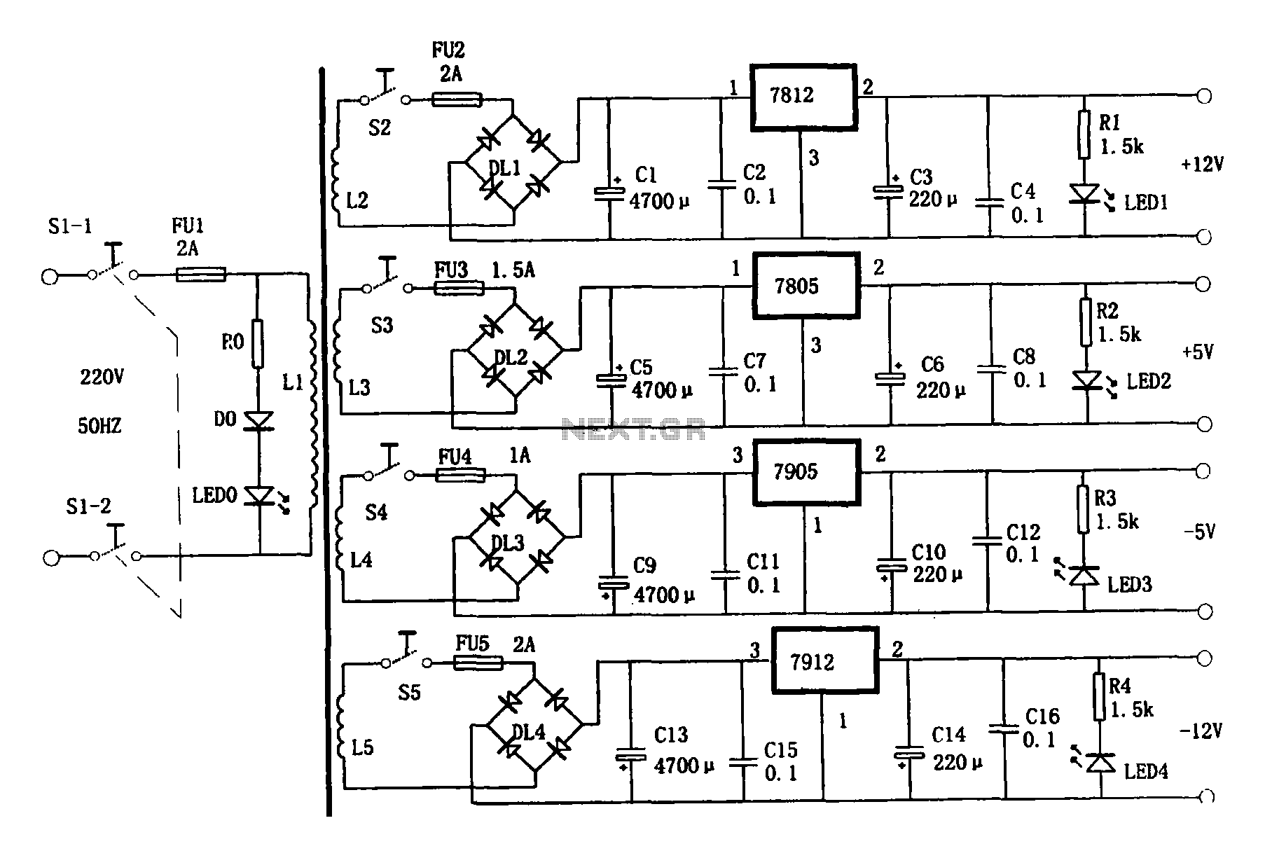
This document presents a multi-output power supply circuit. The circuit utilizes the secondary winding of a transformer and incorporates four voltage regulators: 7812, 7805, 7905, and 7912, providing independent output voltages of +12V, +5V, -5V, and -12V, respectively. Each...