
A typical computer motherboard CPU power supply circuit

The CPU power supply circuit on a computer motherboard is a critical component designed to ensure stable and efficient power delivery to the processor. The main power management chip, RT9241, plays a pivotal role in regulating the voltage supplied to the CPU. It receives a voltage command signal from the CPU itself, which is essential for dynamic voltage scaling, allowing the processor to adjust its power consumption based on workload demands.
The RT9241 processes this command signal through an internal circuit identification mechanism, which determines the appropriate voltage levels required for optimal CPU operation. It generates two distinct phase PWM (Pulse Width Modulation) signals that are crucial for controlling the power output. The use of two different phases helps in reducing ripple voltage and improving efficiency, as well as enhancing the overall performance of the power supply circuit.
These PWM signals are then routed to the power management components, particularly the RT9600 chip, which further processes these signals. The RT9600 is responsible for driving the external field effect transistors (FETs), specifically Q1, Q2, and Q3. These FETs act as electronic switches that modulate the power delivered to the CPU based on the PWM signals received.
By alternating the states of Q1, Q2, and Q3 in response to the PWM signals, the circuit effectively manages the power flow, ensuring that the CPU receives the necessary voltage and current levels for operation while minimizing energy loss. This arrangement not only supports the CPU's performance but also contributes to the overall power efficiency of the motherboard, which is increasingly important in modern computing environments where energy consumption is a significant concern.
In conclusion, the CPU power supply circuit on a motherboard, utilizing the RT9241 and RT9600 chips, exemplifies a sophisticated approach to power management, ensuring that the CPU operates reliably and efficiently under varying loads.A typical computer motherboard CPU power supply circuit A typical computer motherboard CPU power supply circuit, which is mainly composed of the main power supply management ch ip RT9241, two from the power source management and other parts of the chip RT9600. Voltage command signal from the CPU from the RT9241 O ~ feet into by the chip circuit identification processing, by pin output two different phases PWM pulse signals, respectively, by the two from power management Cang backsheet each output processing of two opposite phase PWM signal, the field effect transistors Qi, Q2 and Q3, Q after power to the CPU.
Related Circuits
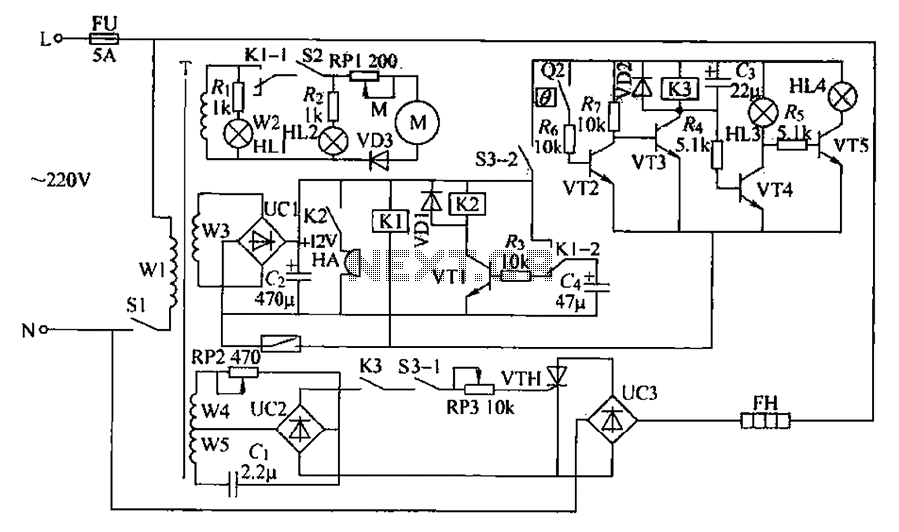
A chemical mixer circuit equipped with stirring speed control, a thermostat, and a timer alarm function is suitable for use in the chemical, steel, and other industries. The circuit includes components for heating, magnetic stirring, motor control, and timing...
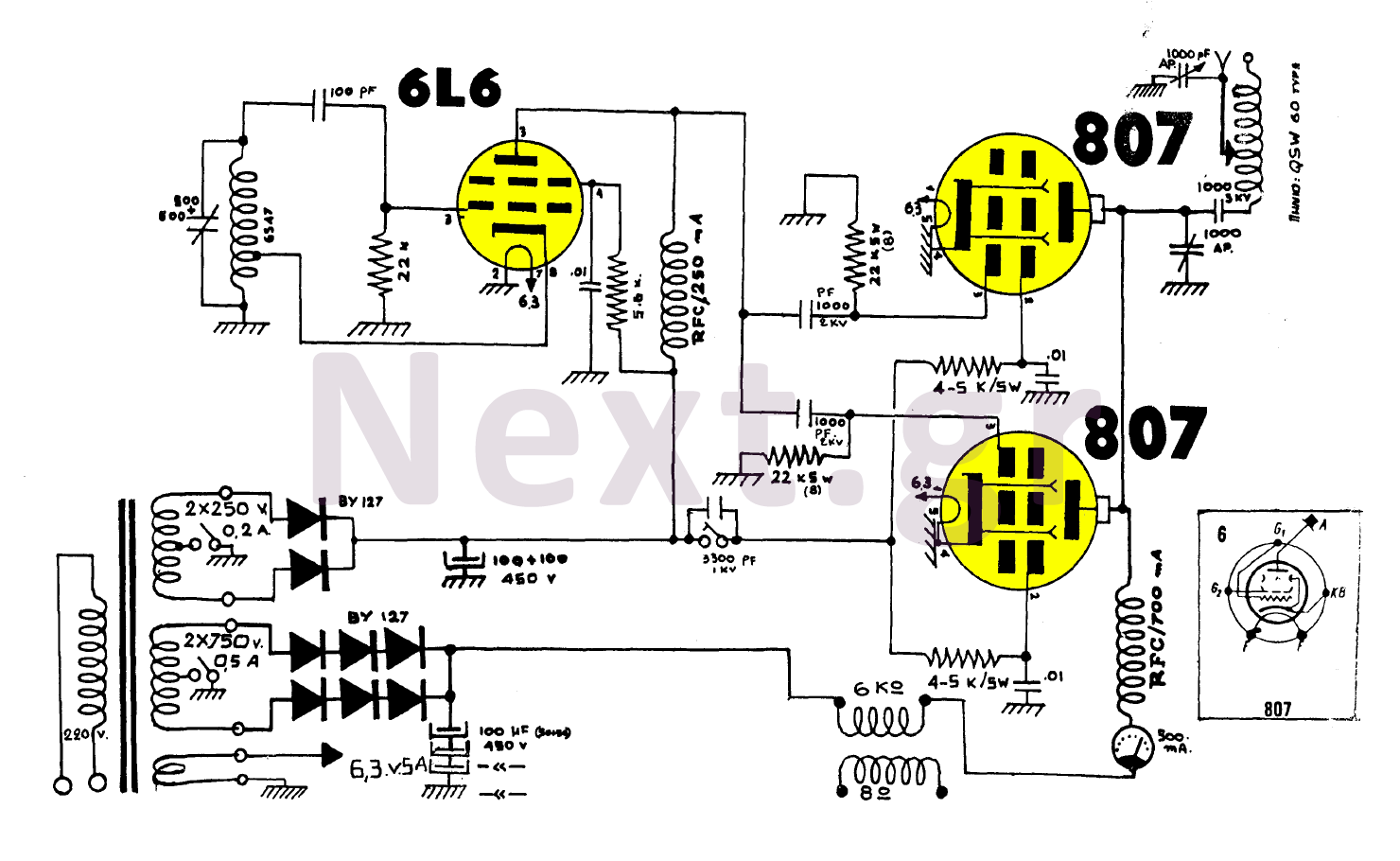
The construction utilizing two 807 tubes is robust and well-known for its performance. This design features high upward voltage and independent coupling on the output tubes, resulting in an increase in output power by several watts. While the output...
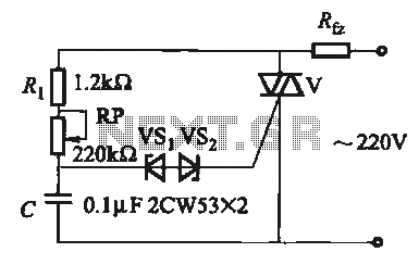
The introduction for a unidirectional thyristor trigger circuit is also applicable to the TRIAC. Several bidirectional circuits are illustrated in Figure 16-28. Figures 16-28 (a) and (b) depict a direct trigger circuit; Figure 16-28 (c) illustrates a dual diode...
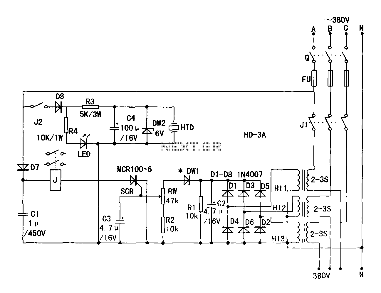
A current transformer H11-3 needs to be constructed. Select a transformer core with a minimum power rating of 2W for the first secondary winding. Use enameled wire with a diameter of 0.12 mm and wind approximately 1000 turns. The...
A 50W isolated forward-converter switching supply for telecom applications is described. Most aspects of the design are discussed. The 50W isolated forward-converter switching supply is engineered to meet the specific demands of telecom applications, where reliability and efficiency are paramount....
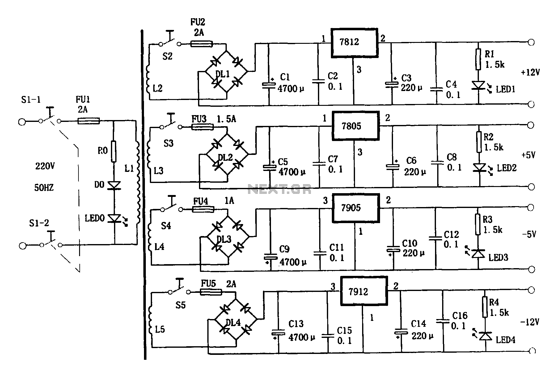
This document presents a multi-output power supply circuit. The circuit utilizes the secondary winding of a transformer and incorporates four voltage regulators: 7812, 7805, 7905, and 7912, providing independent output voltages of +12V, +5V, -5V, and -12V, respectively. Each...