
Chemical mixer circuit

The power circuit is initiated by a power switch (S1) and includes a power transformer (T), a rectifier bridge (UC1), a resistor (R), and a filter capacitor, along with a power indicator (HL1). The heating thermostat circuit is controlled by switch (S3) and includes an electric contact thermometer (Q2), resistors, capacitors (C1 and C2), transistors (VT2-VT5), an electric heater (EH), a thermostat indicator (HL3), a heating indicator (HL4), a diode (VD2), a relay (K3), and potentiometers (RP1 and RP3). The time alarm circuit consists of a transistor (VT1), resistors (R3), a capacitor (C0), a relay (K2), a diode (VD1), a buzzer (HA), and control contacts (K1-2). The stirring motor speed control circuit is managed by switch (S2), potentiometer (RP1), resistor (R2), diode (VD3), stirring indicator (HL2), and the electric motor (M). The timing control circuit is composed of a timer and relays (K1 and Q1).
When the power switch (S1) is turned on, an AC voltage of 220V is supplied by transformer (T) through three groups of AC voltage windings (W2 to W5). The W3 winding provides AC voltage to rectifier (UC1), which filters and supplies +12V power to the timing circuit, delay alarm circuit, and temperature control circuit. Upon activation of the timer (Q1), relay (K1) engages, disconnecting normally closed contacts (K1-1 and K1-2) and connecting the normally open contact to charge capacitor (C1).
Switching on (S2) generates AC voltage from winding (W2), which is rectified by diode (VD3) and limited by resistor (RP1) to supply the stirring motor (M), driving the stirring blades for mixing operations. Activating switch (S3) causes transistor (VT3) to conduct, energizing relay (K3) and connecting its normally open contact. The windings (W4 and W5) generate AC voltage, which flows through capacitor (C1) and resistor (RP2) to be rectified by (UC2) via the normally open contact of (K3) and switch (S3-1). Potentiometer (RP3) provides the trigger voltage to thyristor (VTH), which is activated to supply AC voltage through (UC3) to the electric heater (EH).
The stirring motor speed can be adjusted by varying the resistance of potentiometer (RP1), thereby altering the working voltage and achieving a variable stirring speed. By adjusting resistances (RP2 and RP3), the conduction angle of (VTH) can be modified, which in turn changes the operating voltage of the electric heater (EH), allowing for stepless temperature control.
The electric contact thermometer (Q2) maintains temperature regulation. If the heating temperature falls below the set threshold, (Q2) remains disconnected, preventing power to (V2). Once the temperature reaches the preset value, the contacts of (Q2) close, allowing (VT2) to conduct, which deactivates (VT3) and releases relay (K3). This action cuts off power to (VTH) and stops heating (EH). Concurrently, (VT4) conducts while (VT5) turns off, illuminating indicator (HL3) and turning off (HL4), thus achieving automatic temperature control. Chemical mixer circuit having a stirring speed, thermostat and timer alarm function can be used in chemical, steel and other industries. (1) circuit works heating magnetic stir rer circuit from the power circuit, stirring motor control circuit, heating thermostat circuit, stirring motor speed control circuit, a timing alarm circuit and the timing control circuit, shown in Figure 7-11. Power circuit from the power switch Sl, the power transformer T, rectifier bridge UC1, resistor R., And a filter capacitor power indicator HL1 island components.
Heating thermostat heating circuit by the control switch S3 (S3-1. S3-2), electric contact thermometer Q2, resistors brother ~ Island, capacitance c] and Ca, crystal transistor VT2-VT5, electric heater EH, thermostat indicator HL3, heating indicator HIA, diode VD2, relay K3, potentiometer RI Yi and RP3, bridge rectifiers and thyristors VTH UC2 and UC3 composition. Time alarm circuit by the transistor VT1, resistors R3, capacitor 0, relay K2, the diode VD1, buzzer HA and Kl control contacts Kl-2 components.
Stirred by the stirring motor speed control circuit controls the switch S2, potentiometer RP1, resistor R2, diode VD3, stirring indicator HL2 and electric motor M components. : Timing control circuit by the timer and relays Kl Ql composition. Turn the power switch S], AC 220V voltage by T Buck, produced three groups AC voltage winding W2 ~ W5.
W3 winding -UC1 alternating voltage rectifier, filter G, Zhu is a timing circuit, delay alarm circuit and temperature control circuit provides + 12V power supply. After switching on the timer Ql, relay Kl pull power, Kl-l and Kl-2 normally closed contacts disconnect normally open contact connected, cI charge.
After switching S2, produced on the T winding W2 AC voltage rectified by VD3 and RP1 after limiting supply buck stirring motor M, M drive moving stirring blades into the mixing operation. After switching S3, VT3 conduction, K3 pull power, and its normally open contact connected, Ts W4, w5 winding AC voltage generated by Cl and RP2 flow limit, after UC2 rectified by K3 normally open contact and S3-1.
RP3 provide VTH trigger voltage, the VTH is turned on, AC 220V voltage by UC3 and VTH for the electric heater EH provide operating voltage. Adjust the resistance of RP1 can change the M working voltage level, thereby changing the speed of the stirring speed, variable speed to achieve the purpose.
Adjusting section RP2 and RP3 resistance, can change VTH conduction angle, thus changing EH working voltage level, stepless temperature reaches purposes. When the heating temperature is lower than the value of electric contact thermometer temperature control set Q2, Q2 electric contact in a disconnected state, V2 off.
When the heating temperature reaches the set temperature control Q2, electric contacts Q2 is turned on, so that VT2 conduction, VT3 deadline, K3 release, VTH cut stop, EH power to stop heating. Meanwhile VT4 conduction. VT5 off, HL3 lit, HL4 off, so as to achieve the purpose of automatic temperature control.
Related Circuits
This circuit is fundamentally similar to the channel LED sequencer, with the enhancement of solid-state relays for controlling AC lamps. The relay depicted in the diagram is a Radio Shack 3 amp unit (part no. 275-310), which requires 1.2...
The TDA2822 is a low-power stereo operational amplifier commonly utilized in Walkman devices and headphones. It is capable of delivering an output power of 250 milliwatts. This operational amplifier is particularly suitable for low-volume production applications and serves as...
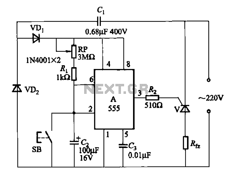
The 555 integrated circuit (IC) is utilized in a delay circuit configuration. It transitions from a high to a low output state when a button (SB) is pressed. The output remains high for a specified delay period before transitioning...
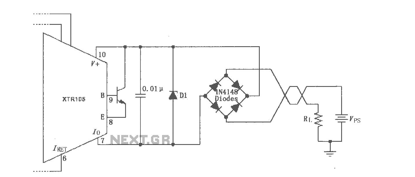
The XTR105 reverse voltage and over-voltage surge protection circuit is illustrated. A Zener diode rated at 36V can be utilized, with options including 1N4753A or 1N6286A. The maximum supply voltage (Vps) should be less than the minimum breakdown voltage...
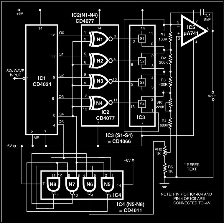
Many electronic devices rely on the shape of signals. Generating square wave signals from sine waves is relatively straightforward, while the reverse process is more challenging. The static square wave-to-sine wave converter circuit can produce an accurate sine wave...
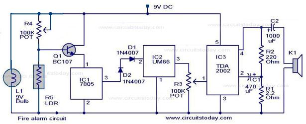
A simple fire alarm circuit utilizes a light-dependent resistor (LDR) and a lamp for smoke detection. The system operates by detecting smoke generated during a fire. An audible alarm is triggered when smoke is present. In the absence of...