
A variable frequency oscillating circuit transistor

The variable frequency oscillator (VFO) circuit described operates at a frequency of 30 MHz, utilizing a combination of transistors and passive components to achieve its functionality. The core of the oscillator is transistor VT1, which is configured to form the primary oscillation circuit. The inductor (LP) connected to the emitter of VT1 plays a crucial role in determining the oscillation frequency in conjunction with the crystal resonator.
The use of varactor diodes in this configuration allows for frequency tuning. By varying the control voltage applied to the varactor diodes, the capacitance changes, which in turn alters the resonant frequency of the oscillator circuit. This tuning capability is essential for applications requiring precise frequency adjustments.
The circuit also includes a 75 pF capacitor, strategically placed in series between the emitter and collector of VT1. This capacitor helps to stabilize the oscillation and enhance the overall performance of the oscillator. The amplified output is taken from the collector of transistor VT3, which is part of a cascading amplifier stage that includes VT2. This multi-stage amplification ensures that the oscillation signal is sufficiently strong for further processing or transmission.
The overall design of the variable frequency oscillator circuit reflects a balance between stability, tunability, and amplification, making it suitable for high-frequency applications in various electronic systems. The careful selection of components and their arrangement is critical for achieving the desired performance characteristics, particularly in maintaining a stable oscillation while allowing for frequency adjustments through the control voltage applied to the varactor diodes.Fig variable frequency oscillator transistor circuit, which is mainly an oscillator, the crystal resonator and varactor circuit by the transistor diode, the output of the ampli fier, typically used to make high-frequency transistor oscillator. 30 MHz transistor circuit inductor LP is connected VT1 emitter circuit, it is connected in parallel and then in series with varactor diodes, and then with 75 p capacitor connected in series between the emitter and collector VT1. VT2, VT3 amplifier constituted after the oscillation signal is amplified by the VT3 collector electrode output.
Changes between V - + - 4 varactor control voltage.
Related Circuits
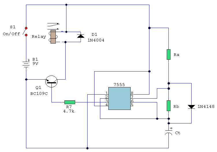
The following circuit illustrates a timer circuit with independent mark and space periods. It is based on the 7555 integrated circuit (IC). The high output duration is calculated by T(on) = 0.7 Ra Ct, while the low output duration...
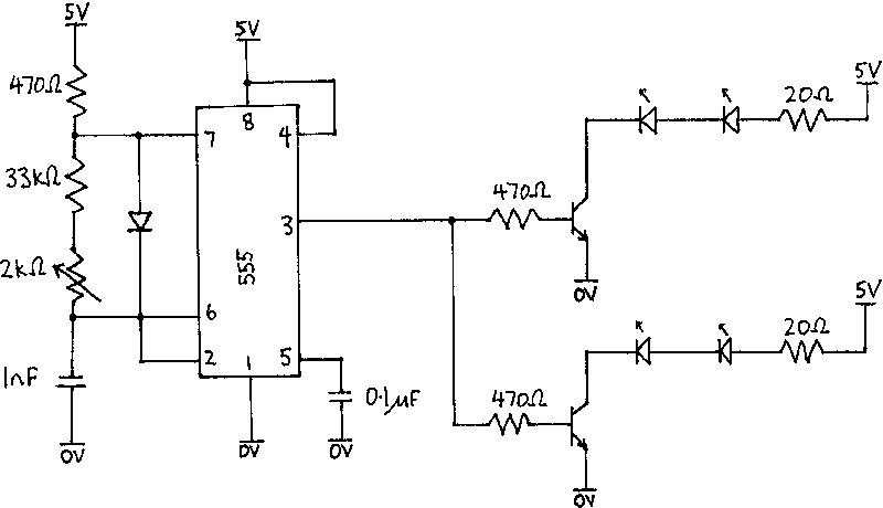
The infrared receiver requires the infrared light to be modulated at 38 kHz, which corresponds to a period of 26 µs. The specifications for the receiver suggested using a 50% duty cycle; however, this configuration did not perform as...
This simple circuit tests speakers, microphones, transformers, and voltage. It is essentially a very low-frequency oscillator that produces extremely short pulses. The sound produced is easy to hear and helps determine the precise direction it originates from, making it...
A circuit involving oscillations is composed of a Houle Wang oscillator that utilizes a transistor configuration with components labeled Ti, n, and n, along with a composition of Q constants for the cycle. The waveform can be modified by...
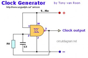
The following diagram represents a Clock Generator circuit that is constructed using NAND Gate logic integrated circuits (ICs). The circuit can utilize either IC 7400 or IC 4011. The 7400 is a TTL (Transistor-Transistor Logic) type, whereas the 4011...
A field effect transistor (FET) voice amplifier has a low input impedance, approximately 1 kΩ, requiring the signal source to provide a constant current signal for operation. Unlike bipolar transistors, FETs are voltage-controlled devices that draw minimal current at...