
Asymmetric Timer Circuit With 7555 IC

The timer circuit utilizing the 7555 IC operates as an astable multivibrator, which continuously switches between its high and low states without requiring any external triggering. The independent mark and space periods allow for flexible timing applications in various electronic projects.
The timing intervals are determined by external resistors (Ra and Rb) and a timing capacitor (Ct). The calculations for the high and low output durations are crucial for achieving the desired frequency of operation. Specifically, T(on) is influenced by the resistance of Ra and the capacitance of Ct, while T(off) is dependent on Rb and Ct. The factor of 0.7 in the formulas accounts for the charging and discharging characteristics of the capacitor in the circuit.
The discharge path is a critical component of the circuit, ensuring that the timing capacitor discharges properly, allowing for consistent timing intervals. The inclusion of a transistor can provide additional control or amplification of the output signal, depending on the circuit's application.
Powering the circuit with a battery ensures portability and ease of use in various settings. A switch is often included to enable or disable the circuit, providing user control over its operation. The diode serves to protect the circuit from reverse polarity, which can occur if the battery is connected incorrectly.
Overall, this timer circuit offers a versatile solution for generating precise timing sequences in hobbyist projects, educational demonstrations, or prototyping environments. The flexibility in setting independent timing intervals makes it suitable for applications such as LED blinkers, tone generators, or pulse width modulation (PWM) signals.The following circuit shows a timer circuit with independent mark and space periods. This circuit based on the 7555 IC. Features: output high is calculated by T(on) = 0. 7 Ra Ct, output low is calculated by T(off) = 0. 7 Rb Ct, astable timer, (on) and (off) values set independently, discharge path. Component: 7555 IC, Resistor, Transisto r, Battery, Switch, Diode, Capacitor. [hobbyprojects. com] 🔗 External reference
Related Circuits
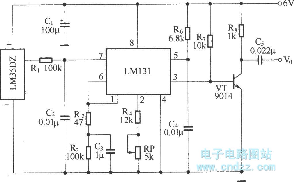
The circuit depicted in the figure integrates a temperature detection system, a temperature-voltage switch, and a voltage-frequency switch to enable remote temperature monitoring. This circuit is connected to a wireless transmission circuit, creating a remote control temperature detection system....
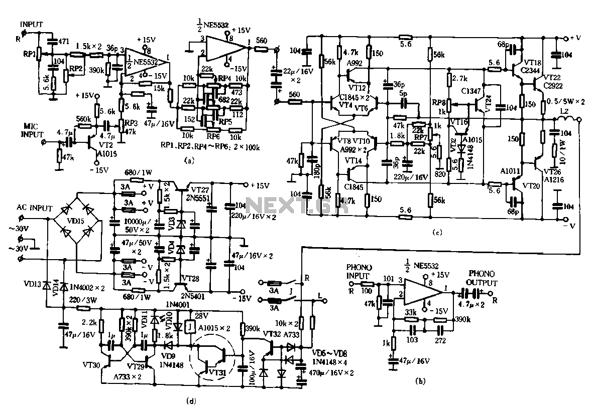
Only the R channel is shown, with the original reference PCB label. Figure (a) illustrates the front tone circuit, which consists of a common negative feedback operational amplifier in an RC circuit configuration. The microphone signal is amplified by...
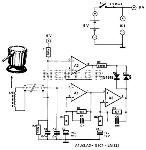
The circuit utilizes the principle that in an RL circuit, the pulse width across the inductor is proportional to the inductance. This circuit indirectly measures the inductance using a digital voltmeter (DVM). The measurement range is approximately 5 to...
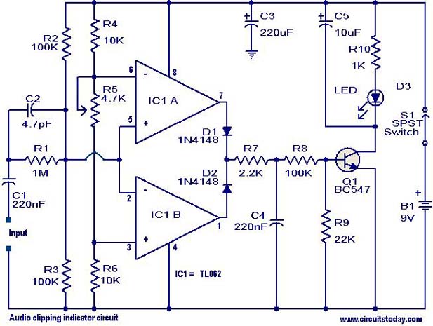
This circuit is designed to detect clipping in a specific waveform. Clipping occurs when the amplitude of a waveform decreases before reaching its expected limit. The circuit activates an LED as an indication that the tested signal is experiencing...
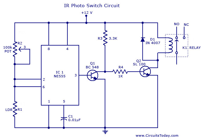
A simple photo switch circuit using the NE555 IC with a diagram and schematic. This photo switch activates a relay when light intensity exceeds a certain threshold. It serves as a light sensor circuit suitable for both home and...
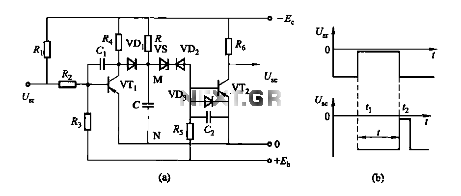
The circuit features a delay action with an instantaneous reset control mechanism. It is categorized into three types: a conducting pipe rechargeable delay circuit, a tube cut-off control rechargeable delay circuit, and a discharge-type delay circuit. In the conducting...