
NAND Gate Clock Generator circuit diagram

The Clock Generator circuit designed with NAND gates serves as a fundamental building block in digital electronics, providing a square wave output that can be used to synchronize operations in various digital systems. In this configuration, the NAND gates are arranged in such a way that they create oscillations, generating a clock signal with a specific frequency determined by the external components connected to the circuit.
For implementing this circuit, a basic understanding of the timing characteristics of the chosen IC is essential. The frequency of oscillation can be adjusted by varying the resistor and capacitor values connected to the NAND gates. Typically, a resistor-capacitor (RC) network is employed to set the time period of the clock signal, where the resistor (R) and capacitor (C) values dictate the charge and discharge times, ultimately influencing the output frequency.
In practical applications, the output clock signal can be utilized in microcontrollers, digital counters, and frequency dividers, among other applications. The choice between the 7400 and 4011 ICs should be made based on the specific requirements of speed and cost for the intended application. The TTL 7400 is preferable for high-speed applications, while the CMOS 4011 may be selected for battery-operated devices where power consumption is a critical factor.
Overall, the Clock Generator circuit is an essential component in digital design, facilitating the timing necessary for synchronous operation in various electronic systems.The following diagram is the Clock Generator circuit diagram which build based on NAND Gate logic IC. You may use IC 7400 or 4011 for this circuit. The 7400 is a TTL type, while 4011 is CMOS type. IC 4011 is cheaper than 7400 but the 7400 is faster than 4011. 🔗 External reference
Related Circuits
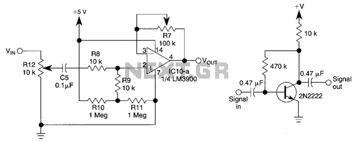
This circuit utilizes one-quarter of an LM3900 to create a simple variable-gain front end for an oscilloscope. R7 serves as the gain control. Additionally, a basic preamplifier is included for applications requiring more than 10X gain. The circuit employs the...
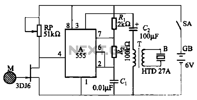
The circuit utilizes a 555 integrated circuit (IC) configured as a non-stable multivibrator. When a sensor detects proximity to a high-voltage electrified body, a piezoelectric ceramic sheet generates an alarm. Additionally, when in proximity to a high-frequency electric field,...
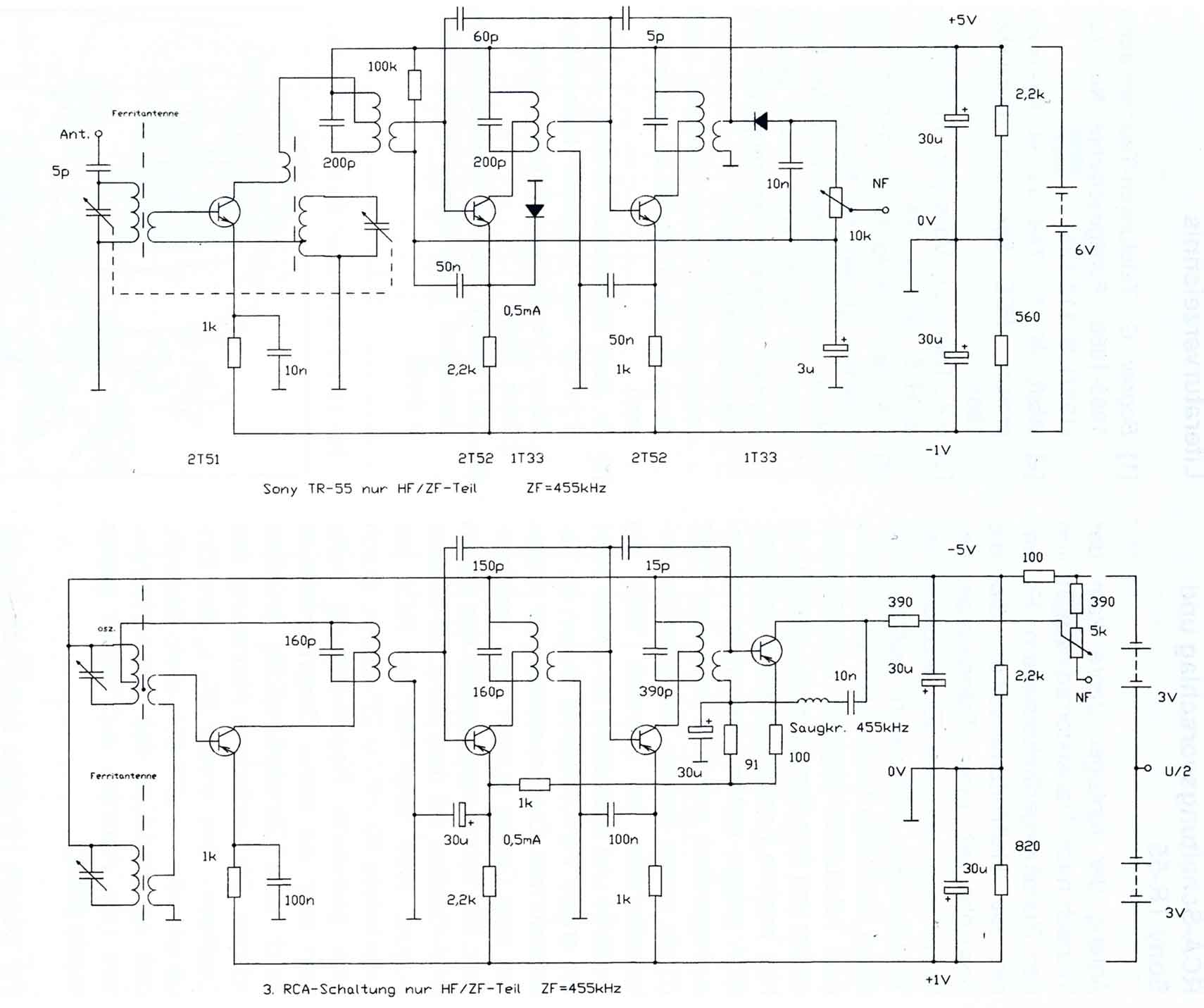
The circuitry of the Regency exhibits several unique characteristics. Notable features include the self-oscillating mixer stage, the base bias voltage of the second IF stage derived from the AF power stage, an unusual IF frequency of 262 kHz, and...
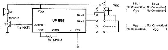
This siren alarm circuit diagram utilizes the specialized integrated circuit (IC) UM3561, which is a low-power CMOS large-scale integration (LSI) device specifically designed for such applications. The UM3561 incorporates all necessary components, including an oscillator, selector circuits, and programmed...
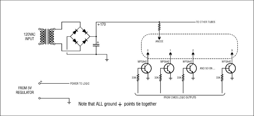
The high voltage supply will function, but for safety and to prevent accidental damage during troubleshooting with an oscilloscope, it is highly recommended to use an isolation transformer on the 120VAC input. A small 1:1 transformer rated at 30VA...
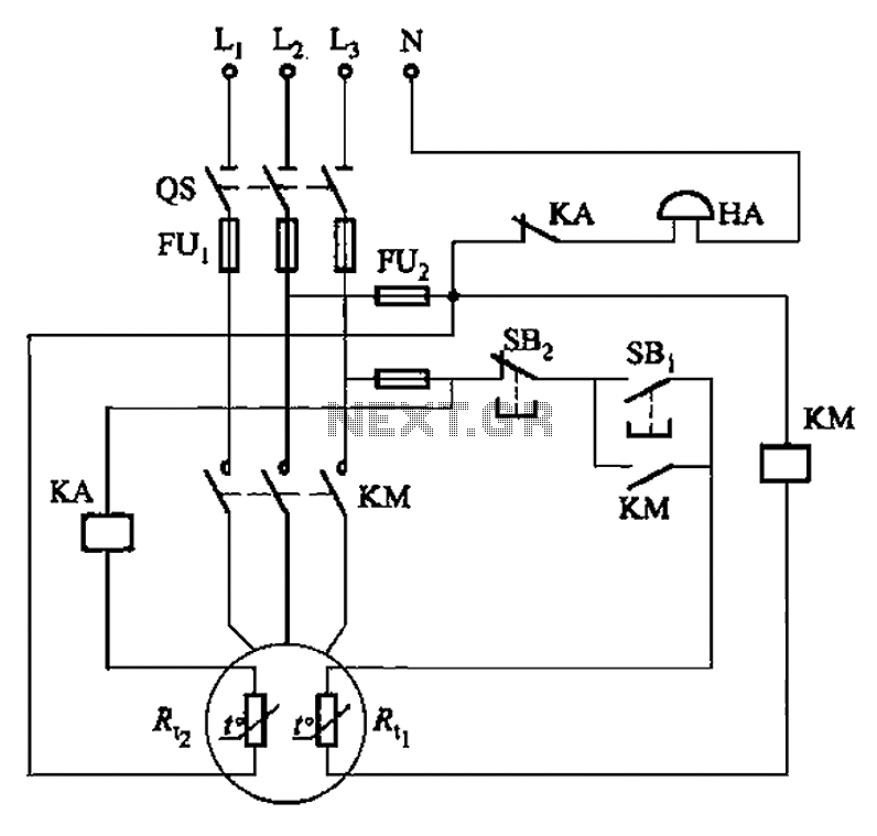
The circuit illustrated in Figure 4-2 employs two thermal resistors. One, designated as Rc, functions as overload protection, while the other, labeled Rt, serves as an alarm. The circuit in question integrates two thermal resistors to monitor temperature changes and...