
VW CAR PASSAT ENGINE CONTROL AND AUTOMATIC SOLENOID ELECTRICAL WIRING CIRCUIT

The electrical wiring diagram for the 1993 VW Passat serves as a crucial reference for understanding the interactions between various components within the vehicle's engine management and automatic transmission systems. The Engine Control Module (ECM) is the central unit that processes inputs from various sensors, such as the coolant temperature sensor and throttle position sensor, to regulate engine performance and efficiency. The Automatic Control Unit (ACU) manages the automatic transmission's shift points and overall operation, relying on feedback from the shift lock solenoid and other related components.
Connections illustrated in the diagram include a multi-function switch that allows the driver to control multiple functions, such as lighting and wipers, while the fuse relay panel provides protection against overloads and short circuits in the electrical system. The knock sensor plays a critical role in detecting engine knock, enabling the ECM to adjust ignition timing for optimal performance.
The throttle valve potentiometer and idle air control valve are essential for maintaining engine idle speed and responsiveness to throttle inputs. The inclusion of the ignition booster ensures that the ignition system operates efficiently, providing a reliable spark for combustion. Furthermore, the diagram outlines the routing of wiring for the carbon canister and evap emission on/off valve, which are vital for controlling emissions and maintaining compliance with environmental regulations.
In summary, this wiring diagram is an indispensable tool for technicians and engineers working on the 1993 VW Passat, offering a comprehensive view of the electrical connections and functional relationships between critical engine and transmission components. Proper understanding and utilization of this diagram facilitate effective troubleshooting, maintenance, and repair of the vehicle's electrical systems.1993 VW Passat Engine Control Module, Automatic Control Unit, and Automatic Solenoid Electrical Wiring Diagram are shown in the following figure. It shows the connection and wiring between each parts and component of Engine Control Module, Automatic Control Unit, and Automatic Solenoid system of the vehicle such as the multi-function switch, fuse/
relay panel, knock sensor, coolant temperature sensor, shift lock solenoid, starter interlock/back up lit relay, automatic control computer clutch shut off relay, automatic control unit, automatic solenoids, program switch, throttle position sensor, full throttle switch, idle switch, throttle valve potentiometer, ignition booster, distributor firing order, engine control module, carbon canister, cold starter, idle air control valve, evap emission on/off valve, and many more. 🔗 External reference
Related Circuits
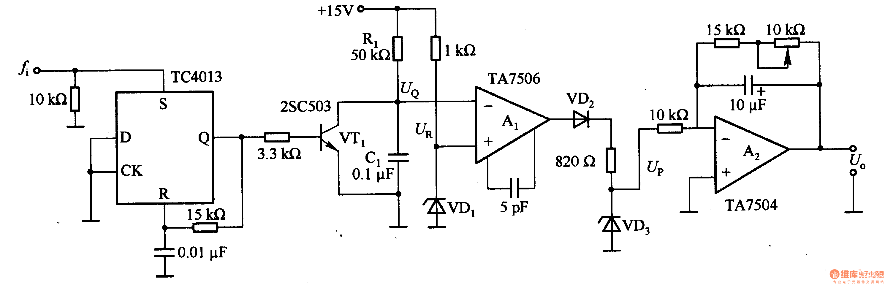
This circuit can convert an input frequency ranging from 0 to 100 Hz into an output voltage of 0 to 10 V. It utilizes the TC4013 monostable multivibrator to shape and amplify the input pulse, which has a width...
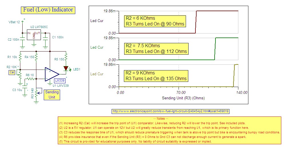
Research indicates that the sender will register a resistance of 100 ohms when the fuel tank is empty, making a trigger reading of 80 ohms optimal. The fuel gauge sender is a critical component in monitoring the fuel level within...
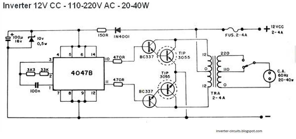
This schematic represents a simple 40W inverter that converts 12V to 220V. It has been functional for four years. The core component of the circuit is a CD4047 integrated circuit (IC) configured as an astable multivibrator. The resistance and...
This radio receiver can operate with any of the following transistors: ZN414, MK484, or TA7642. The radio receiver circuit is designed to utilize a variety of transistors, specifically the ZN414, MK484, and TA7642, which are commonly used in low-power AM...
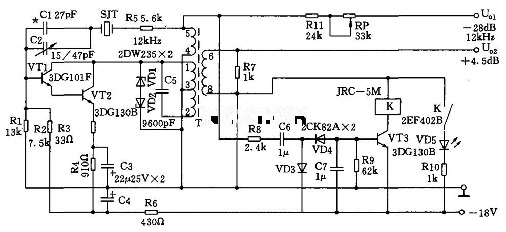
The circuit depicted is a 12 kHz intermediate frequency oscillator designed for an alarm system. It employs a variable feedback oscillation circuit where the oscillation frequency is primarily determined by a quartz crystal. Capacitors C1 and C2 are used...
The 1-megohm resistor protects the FET from potential damage caused by accidental sparks to its gate lead. The circuit functions adequately without this resistor; however, it is advised not to intentionally apply a charge to the gate wire using...