
12V to 220V converter circuit Schematic Diagram

The circuit design of this DIY voltage converter employs a CMOS 4047 integrated circuit, which is widely recognized for its versatility in generating square wave signals. In this application, the 4047 operates in astable mode, producing a continuous output waveform that serves as the basis for converting the input DC voltage to AC voltage.
At the heart of the circuit, the 4047's output pins (10 and 11) deliver a symmetrical rectangular waveform. The frequency of this waveform can be fine-tuned through the use of resistors and capacitors connected to the 4047, allowing for a flexible output frequency that can range from 50Hz to 400Hz. This feature is particularly useful for adapting the converter to different types of appliances that may require specific operating frequencies.
The generated signal is then fed into two Darlington transistor pairs, which are configured to amplify the current of the signal. This amplification is crucial for driving the transformer effectively, ensuring that sufficient power is delivered to the load. The transformer used in this design is a step-up transformer rated at 2x10V and 60VA, which is capable of converting the low voltage signal into a higher voltage output of 220V AC at its secondary terminals.
The transformer plays a pivotal role in isolating the high voltage output from the input circuit, providing safety during operation. The output voltage can be utilized to power various household appliances that operate on AC voltage, although it is essential to note that this converter is not intended for professional applications and may not meet all regulatory standards for commercial devices.
Overall, this DIY voltage converter represents an accessible solution for hobbyists and enthusiasts looking to create their own power conversion systems for light-duty applications. Proper attention to component ratings and safety precautions is advised to ensure reliable and safe operation.This DIY 12V to 220V voltage converter is build with CMOS 4047 that is the main component of this small voltage converter that transforms a 12V DC into 220V AC. 4047 is used as a astable mutivibrator, at pins 10 and 11 will have a symmetrical rectangular signal wich is amplified b 2 Darlington transistors and finally reach the secondary coil of ma
ins transformer ( 2x10V / 60VA ). At the main voltage converter transformer terminals it will be 220V. With the help of P1 the output frequency can be adjusted between 50Hz to 400Hz. Although this is not part of any professional dc ac converters it can be used quite effective on some home appliances. 🔗 External reference
Related Circuits

A 4-wire resistive touch screen utilizes an ADS7846 interface circuit. The ADS7846 analog chip incorporates electronic switches and a successive approximation A/D converter. The analog switch chip controls the switching of the X+ (or Y+) positive supply terminal, while...
The main purpose of this design is to address a minor flaw in the widely used Fridge Door Alarm circuit, which has been available on this website since 1999 and has been constructed by many hobbyists. This circuit ceases...
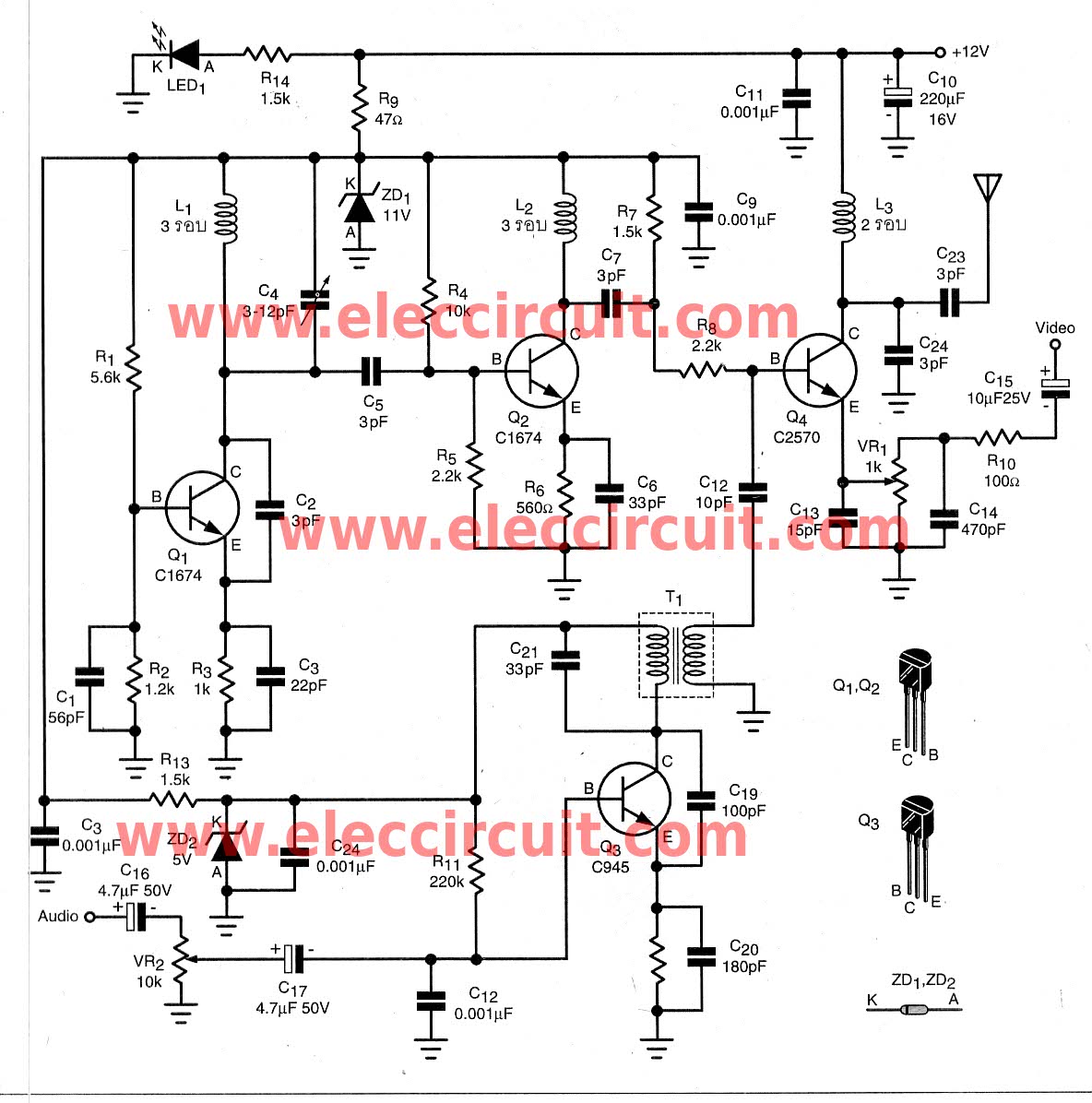
To transmit video and audio signals to multiple televisions simultaneously, a video amplifier splitter utilizing a transistor can be employed. A video amplifier splitter is an electronic device designed to distribute a single video and audio signal to multiple output...

The Door Buzzer circuit utilizes an IC 555 to generate a sound resembling an electric bell. When the switch S1 is pressed, a loud sound is produced. This circuit is designed to be simple and requires minimal components. It...
This simple water detector circuit utilizes alternating voltage to prevent electrode corrosion. It is easy to construct and employs N1 as a trigger Schmitt gate to generate the AC signal. When a conductive substance, such as an aqueous solution,...

The circuit consists of dual drive integrated circuits (ICs) utilized in a 10 LED level meter configuration. The schematic features two TLM8101 driver ICs, which can be employed as alternatives. The 10 LED level meter circuit is designed to provide...