
A709 a simple differential amplifier circuit diagram

The described differential amplifier utilizes an operational amplifier (op-amp) to amplify the difference between two input voltages, Vi1 and Vi2. The circuit configuration includes resistors R1, R3, and R4, which are critical for establishing the gain of the amplifier and determining the input impedance.
In this configuration, Vi1 is fed into the inverting terminal of the op-amp through resistor R1, while Vi2 is connected to the non-inverting terminal via resistors R3 and R4, which form a voltage divider. This arrangement allows for the adjustment of the gain and the balance between the two input signals.
The output voltage Vo can be expressed mathematically as Vo = (R2 / R1) * (Vi2 - Vi1), where R2 is the feedback resistor connected from the output to the inverting input. The gain of the differential amplifier is determined by the ratio of the feedback resistor and the input resistor.
Moreover, the design of this circuit ensures that common-mode signals (signals that are present on both inputs) are effectively rejected, making the differential amplifier particularly useful in applications where noise reduction is critical. The ability to amplify only the difference between the two input signals while rejecting common-mode noise is a key advantage of this configuration.
In practical implementations, careful selection of resistor values is essential to achieve the desired performance characteristics, including bandwidth and signal fidelity. This circuit finds applications in various fields, including audio processing, sensor signal conditioning, and instrumentation, where accurate and stable voltage differences need to be measured and amplified. As shown for the simple differential amplifier circuit. Two input signals Vi1 and Vi2 respectively by R1 and R3, R4 voltage divider circuit added to the op amp input. Vi1 appli ed to the inverting input of the op amp, Vi2 applied to the non-inverting input and the output voltage Vo and Vi1, Vi2 has the following relationship:
Related Circuits
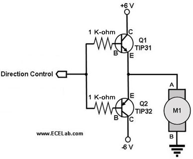
The following circuit illustrates a two-transistor DC motor driver circuit diagram. This circuit utilizes the TIP32 transistor. Features: operates in... The two-transistor DC motor driver circuit is designed to control the operation of a DC motor using two NPN transistors,...
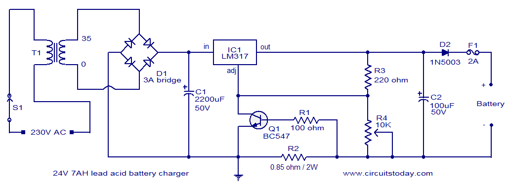
This lead-acid battery charger circuit is designed based on a request from Mr. Devdas C. His requirement was for a circuit that could charge two 12V/7AH lead-acid batteries connected in series. He did not specify the number of cells...
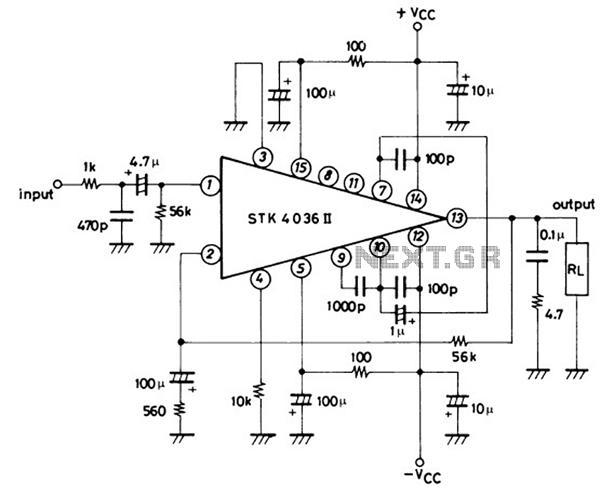
This is a 50-watt audio power amplifier circuit based on the single IC STK4036II. A heatsink is required to prevent overheating of the IC. The amplifier circuit provides good sound quality at an affordable price and is easy to...
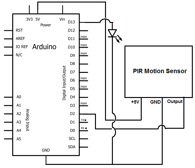
Once the motion sensor detects motion, the Arduino can be programmed to activate an LED, turn on a motor, sound a buzzer, etc. In this circuit, for simplicity, an LED will be turned on when the motion sensor detects...
Top octave generators are known for being economical and compact compared to other tone generation methods. However, their near-perfect tuning often leads to chords that sound flat, particularly in organs where certain stops may not enhance the overall sound....
An infrared (IR) sensor or detector circuit diagram utilizing a 555 integrated circuit (IC), primarily employed as a water level or liquid level sensor and proximity detector circuit. The described circuit employs a 555 timer IC configured in a monostable...