
Infrared (IR) Sensor/DetectorCircuit using 555 IC
 Sensor/DetectorCircuit using 555 IC")
The described circuit employs a 555 timer IC configured in a monostable or astable mode to facilitate the detection of infrared signals. The IR sensor consists of an IR LED and a photodiode or phototransistor. The IR LED emits infrared light, which is reflected back to the photodiode or phototransistor when an object, such as a liquid surface, is present within the detection range.
In the water level sensing application, the circuit is designed to detect the presence of water by measuring the change in the infrared light reflected back to the photodetector. When the water level rises to a certain point, the reflected IR light intensity increases, triggering the 555 timer to output a high signal. This output can then be used to activate an indicator, such as an LED or a relay, to signal that the water level has reached a desired threshold.
For proximity detection, the circuit can be adjusted to sense the presence of nearby objects without physical contact. The distance at which the IR sensor operates can be modified by changing the values of the resistors and capacitors in the circuit. The output of the 555 timer can be configured to drive other components, such as alarms or automated systems, based on the proximity of the detected object.
Overall, this IR sensor circuit using a 555 IC is versatile and can be adapted for various applications, including liquid level monitoring and object detection, making it a valuable component in electronic projects.An Infrared or IR sensor/detector circuit diagram using 555 IC used mainly as Water level or Liquid level sensor and proximity detector circuit.. 🔗 External reference
Related Circuits
The circuit diagram is designed to control audio tone. This circuit utilizes the TDA 1524 tone control integrated circuit (IC), which encompasses controls for balance, bass, treble, and volume within a single component. A potentiometer is employed in series...
For beginners in microcontroller projects who are unsure where to start, this project serves as one of the simplest options available. It provides a clear understanding of programming a microcontroller. Often, one may glance at a watch and ponder,...
Wilf Rigter simplified this circuit a bit, made it phototropic, and doubled it up to yield a photopopper design in a post later the same day. I’ve got this design written up elsewhere in the library. The circuit described is...
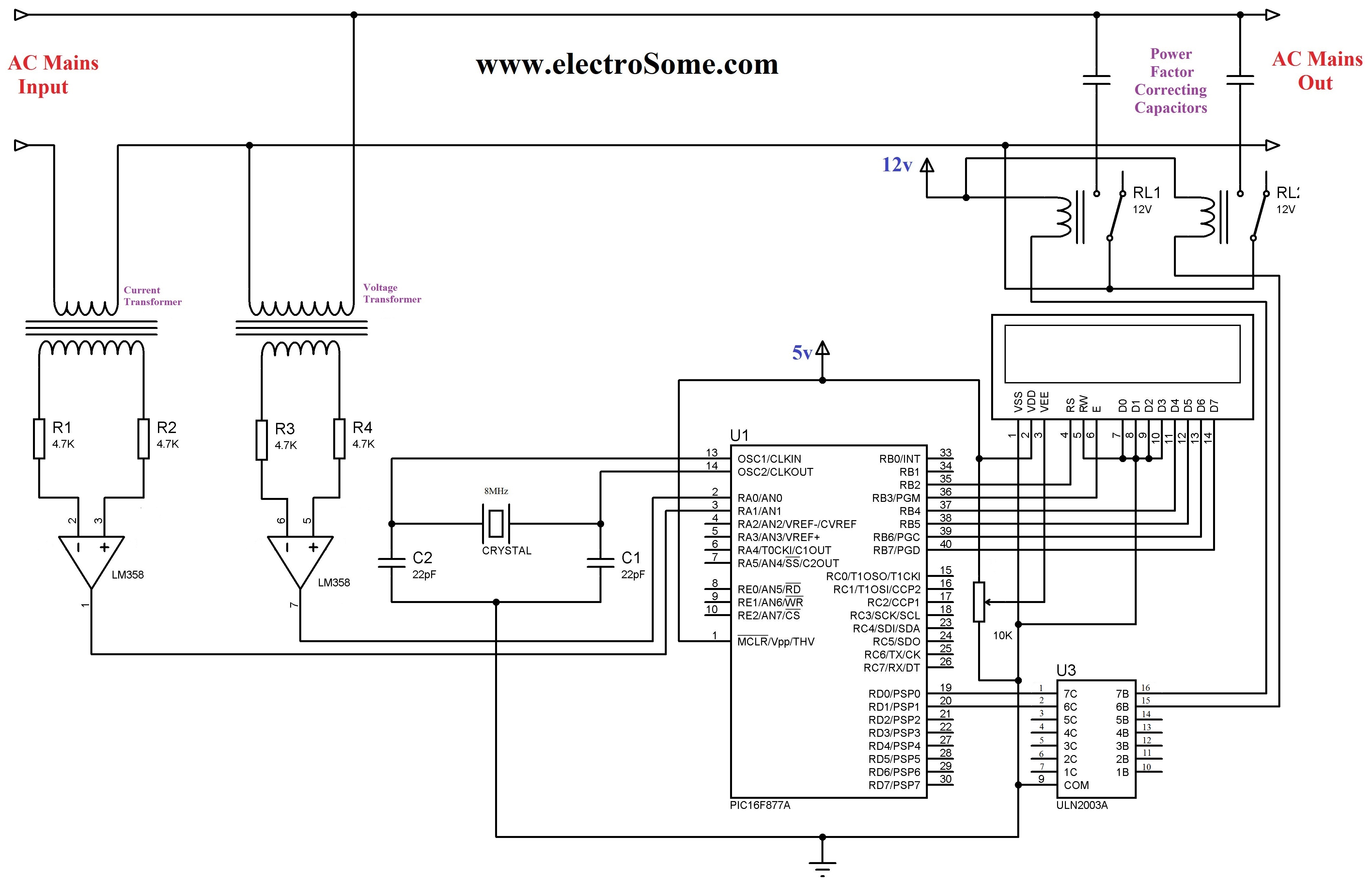
The 230 V, 50 Hz supply is stepped down using a voltage transformer, while a current transformer is utilized to extract the current waveforms. The output of the voltage transformer corresponds to the voltage across the load, and the...
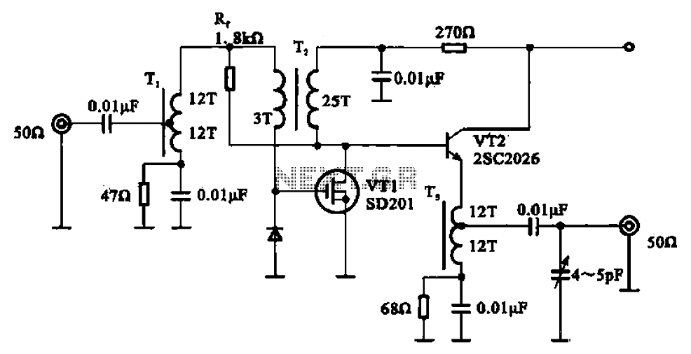
A broadband amplifier circuit utilizing a negative feedback amplifier configuration is presented. This circuit employs transformer coupling and a combination of amplifying sections and field-effect transistors (FETs). The input signal is applied to the center tap of the transformer...
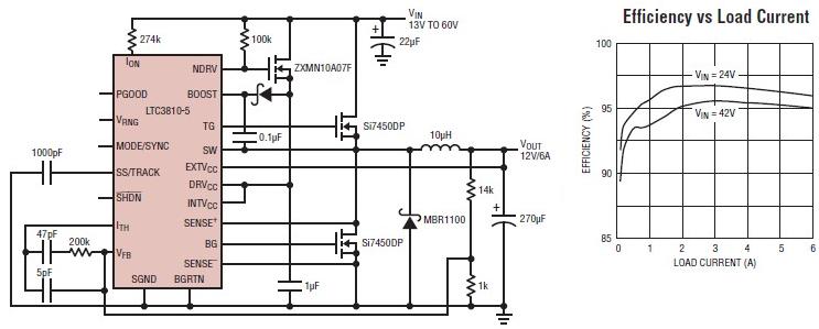
The LTC3810-5 synchronous step-down switching regulator controller allows for the design of a straightforward 12-volt switching power supply electronic project with minimal external components. This controller can directly reduce voltages from up to 60V, making it suitable for telecommunications...