
Absolute value amplifier

This circuit utilizes operational amplifiers (op-amps) to achieve its functionality. The non-inverting amplifier configuration is employed for positive input signals, where the output voltage is a scaled version of the input voltage, determined by the feedback and input resistors. The gain of this configuration can be set using resistors R1 and R2, following the formula: Gain = 1 + (R2/R1).
For negative input signals, the circuit switches to an inverting amplifier configuration. In this mode, the input signal is applied to the inverting terminal of the op-amp, and the output is inverted and scaled based on the same resistor values. The gain for the inverting configuration is given by the formula: Gain = -(R2/R1), leading to a negative output voltage that corresponds to the negative input.
The circuit's performance, particularly its accuracy for input voltages below 1V, indicates limitations in the op-amp's specifications or the design itself. Factors such as the op-amp's input offset voltage, bias current, and noise characteristics can significantly affect the output for low voltage signals. In applications where precision is not critical, this circuit can still provide a useful amplification function, making it suitable for various signal processing tasks where high fidelity is not required.
Design considerations should include selecting an op-amp with suitable characteristics for the intended application, ensuring power supply levels are adequate to accommodate the expected output range, and carefully choosing resistor values to optimize gain while maintaining stability and minimizing distortion. Additionally, implementing bypass capacitors on the power supply pins can enhance performance by reducing noise and improving transient response.The circuit generates a positive output voltage for either polarity of input. For positive signals, it acts as a noninverting amplifier and for negative signals, as an inverting amplifier The accuracy is poor for input voltages under 1V, but for less stringent applications, it can be effective.
Related Circuits
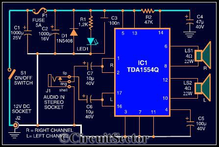
The circuit diagram illustrates a robust stereo amplifier capable of delivering 22W of power. It is based on the widely used single-chip audio power amplifier TDA1554Q (IC1), which is configured as two 22W stereo bridge amplifiers. While listening to...
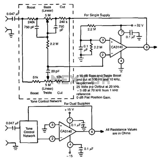
This circuit utilizes the high slew rate, high input impedance, and high output-voltage capability of the CA3140 BiMOS operational amplifier. It also offers mid-band unity gain using standard linear potentiometers. The circuit design leverages the characteristics of the CA3140 BiMOS...
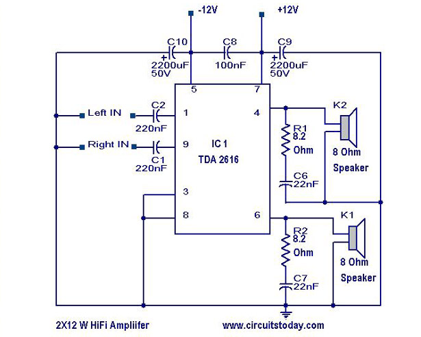
A simple Hi-Fi amplifier circuit diagram with a schematic for creating an audio amplifier, designed using the TDA 2616 integrated circuit (IC), which is a stereo power amplifier. It is suitable for use with radios, tape players, and televisions,...
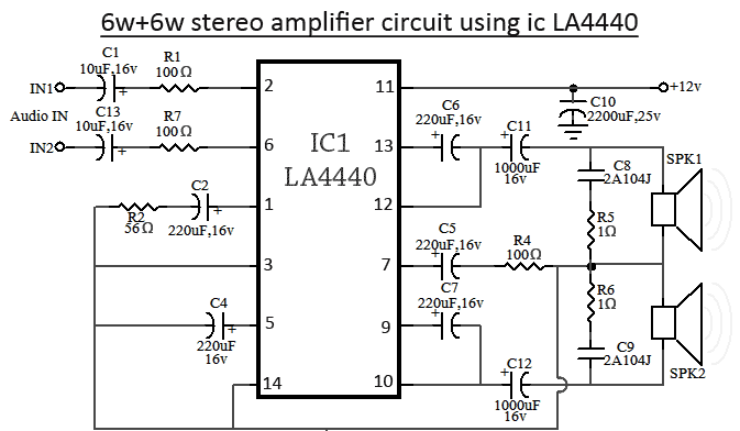
The LA4440 is a dual-channel audio amplifier integrated circuit (IC) that operates in two modes: stereo amplifier mode and bridge amplifier mode. This monolithic linear IC is produced by Sanyo. The circuit includes both amplifier modes utilizing the LA4440....
The SSM2306 is a fully integrated, high-efficiency, Class-D stereo audio amplifier designed to maximize performance for portable applications. The application circuit requires minimal external components and operates from a single supply voltage ranging from 2.5 V to 5.0 V....
This is a 25-watt basic power amplifier designed for ease of construction at a reasonable cost. It offers superior performance compared to standard STK module amplifiers commonly found in most mass-market stereo receivers produced today. The 25-watt basic power amplifier...