
Hi Fi Amplifier Circuit 2X12 Watts

The TDA 2616 is a high-performance integrated circuit designed for audio amplification applications. It is specifically tailored for driving speakers in consumer electronics like radios, tape players, and televisions. The circuit utilizes this IC to achieve a stereo output configuration, allowing it to drive two channels simultaneously.
The amplifier circuit typically includes a power supply section, input signal conditioning, and the TDA 2616 IC configured to operate in a class AB mode. The power supply section should provide a dual voltage supply, often around ±14 to ±16 volts, to ensure optimal performance. The input stage may include capacitors for coupling and resistors for setting the gain, ensuring that the audio signal is appropriately conditioned before amplification.
The TDA 2616 features built-in protections against short circuits and thermal overloads, enhancing the reliability of the circuit. External components such as capacitors and inductors may be included to filter out noise and stabilize the power supply, further improving audio quality.
The output stage of the circuit is designed to deliver 2 x 12 watts of power, which is suitable for driving standard speakers in home audio systems. The design may also include feedback loops to enhance linearity and reduce distortion, ensuring that the amplified audio signal remains faithful to the original input.
In summary, the described Hi-Fi amplifier circuit using the TDA 2616 IC provides a robust solution for audio amplification needs, combining simplicity in design with effective performance for various audio applications.A simple Hi Fi amplifier circuit diagram with schematic for making audio amplifier,design using TDA 2616 IC, which is a stereo power amplifier, useful for radio,tape and television. Delivers 2*12 watts net 24 watts.. 🔗 External reference
Related Circuits
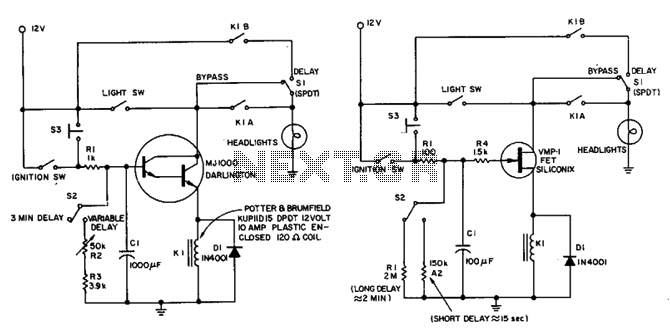
This circuit maintains the headlights of an automobile in an on state temporarily. It also ensures that the lights turn off automatically, even if the user forgets to switch them off manually. The shut-off delay is activated only when...
A simple 9 Volt, 2 amp power supply utilizing a single integrated circuit (IC) regulator. This circuit is straightforward, as the regulator handles the majority of the work. The component used is the 7809 voltage regulator. The circuit consists primarily...
This 555 timer circuit activates a relay upon pressing a button. The threshold and trigger inputs, pins 2 and 6, are maintained at half the supply voltage by two 10K resistors. When the output is high, a capacitor charges...
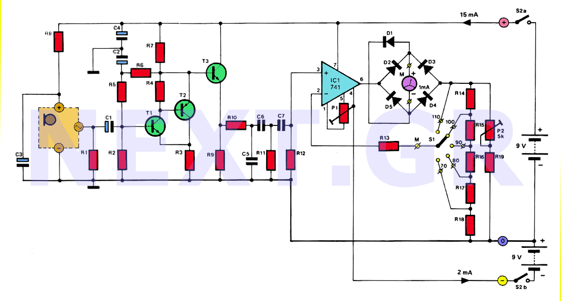
The human ear can detect sounds ranging from 20Hz to 20KHz, with the normal range typically between 100Hz and 13KHz, depending on an individual's age and health. For accurate measurements, a range of 20Hz to 20KHz is used. Sounds...
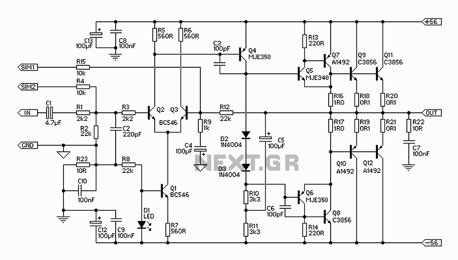
The 300W amplifier circuit presented is a conventional design. It includes connections for the internal SIM and incorporates filtering for RF protection (R1, C2). The input is facilitated through a 4.7µF bipolar capacitor, which offers substantial capacitance in a...
Schematic and description of a simple and easy-to-build NiCd and NiMH battery charger circuit that is capable of charging multiple NiCd and NiMH batteries. The circuit for the NiCd and NiMH battery charger is designed to be straightforward, allowing for...