
AC contactor DC capacitive circuit a run

The AC contactor switch operates by controlling the flow of electrical current in an AC circuit, utilizing DC or pulse DC excitation to enhance efficiency. The incorporation of DC excitation allows for a reduction in the overall energy consumed by the electromagnet, which is critical in applications requiring prolonged operation. The reduction in power consumption is achieved through the elimination of short circuit effects and core losses, which are prevalent in traditional AC systems.
The design of the AC contactor DC capacitive circuit involves several key components, including the contactor itself, capacitors, and resistors. The capacitors serve to store electrical energy, while the resistors help to limit the current flow and manage the thermal characteristics of the circuit. The specified capacitance range of 1 to 6 µF is suitable for various operational scenarios, providing flexibility in circuit design. The resistance values, ranging from 5.1 to 27 ohms, are essential for optimizing the performance of the circuit, as they influence the current draw and heat generation within the system.
Furthermore, the relationship between capacitance and resistance is critical for determining the efficiency of the contactor circuit. A higher capacitance allows for greater energy storage, which can be advantageous in applications that require rapid switching or high inrush currents. However, this must be balanced against the resistance, as lower resistance values can lead to increased power consumption, necessitating careful consideration during design.
Overall, the implementation of an AC contactor switch with DC excitation presents a viable solution for reducing power consumption, noise, and thermal buildup, thus enhancing the longevity and reliability of electromagnetic systems.AC contactor switch to DC or pulse DC excitation can subtract short ring and core power consumption, thereby greatly reducing the power consumption of the electromagnet, and ca n eliminate the noise, but also can reduce the temperature rise of the coil, extending its life. AC contactor DC capacitive circuit has run a variety of types, as shown in FIG. C- capacitance is generally 1 ~ 6 TJ, F, 630V, R- resistance is generally 5.1 ~ 27fl, 10 ~ 30W. Contact capacity, the greater the capacity C, R resistance is smaller, but the greater the power.
Related Circuits

A biaxial magnetic field sensor application circuit is illustrated in the figure. This circuit utilizes a biaxial magnetic sensor HMC1002 along with two AMP04 operational amplifiers (A1, A2) to measure the magnetic field in both the X-axis and Y-axis...
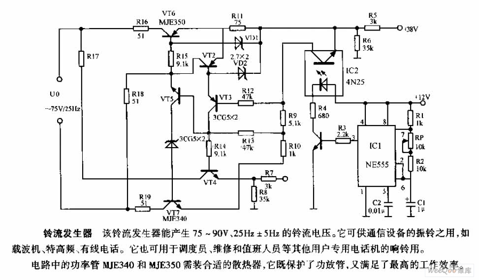
The ring current generator can produce a ringing current voltage of 75-90V and 25Hz ± 5Hz. It is suitable for use in vibrating rings in communication devices, such as carriers, ultrahigh frequency systems, and wire telephones. Additionally, it can...
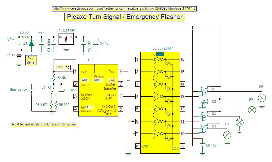
This is a car alarm simulator that uses an LED as a simulation output. This simple circuit can indicate whether a car is running or not by detecting the voltage difference when the car is on or off. This...
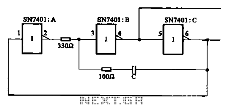
The clock signal generating circuit utilizes an RC configuration, commonly applicable in most TTL systems. This circuit requires a set of six inverters, specifically three inverters from the SN7401 series. The clock frequency is determined by the values of...
Access to the resistors was available, and measurements indicated an open circuit when disconnected from any ground or input source. The circuit in question involves resistors that have been verified for accessibility. When measured in isolation—meaning they are not connected...
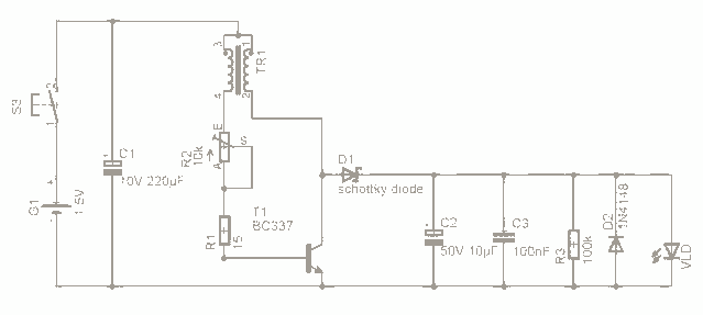
For the past few days, research has been conducted on an intriguing boost circuit known as the Joule Thief. The original schematic can be found through online resources. The Joule Thief is a simple yet effective boost converter circuit designed...