
Ac Current Indicator

The described circuit employs a dual op-amp integrated circuit, which serves as the core component for signal amplification and processing. The first op-amp is configured as a rectifier, converting the alternating current (AC) signal into a direct current (DC) signal. This is typically achieved using a precision rectifier configuration, which allows for accurate measurement of the AC signal even at low levels.
The output from the rectifier is then fed into an emitter-follower stage, which provides a high input impedance and a low output impedance. This configuration ensures that the LED indicator receives sufficient current to illuminate without significantly loading the rectifier output. The LED serves as a visual indicator of AC current presence, lighting up in response to the detected signal.
The inductor L1 is crucial for the circuit's operation. By using a pick-up coil with 100 to 200 turns of #28 gauge wire, the circuit can effectively sense the AC magnetic field generated by current-carrying conductors. The choice of a 2-inch diameter core allows for a balance between sensitivity and physical size, making it suitable for applications such as tracing AC lines behind walls.
This circuit can be particularly useful for electricians and technicians, enabling them to safely detect and trace AC current flow without direct electrical contact. The design emphasizes simplicity and effectiveness, ensuring that users can identify AC lines and monitor current flow in various environments. Using a dual op amp driving a rectifier and emitter-follower, this circuit indicates ac current on an LED. Ll is an au dio transformer winding using a pick-up coil, or 100 to 200 turns of #28 gauge wire 2" in diameter, etc. The circuit can trace ac lines behind walls, etc. or detect ac current flow.
Related Circuits
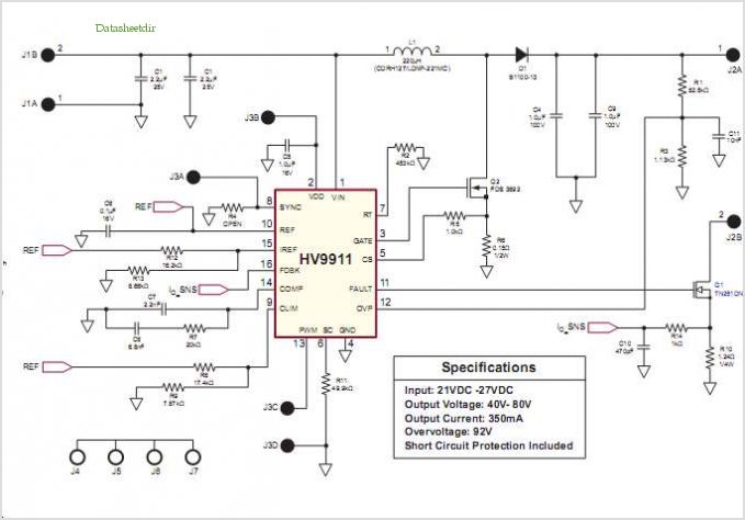
Conventionally, a MOSFET with a voltage rating of 1500V or a Half-Bridge configuration utilizing two MOSFETs rated at 800-900V is employed for Switch Mode Power Supply (SMPS) applications that require input voltages exceeding 380Vac. However, these methods present challenges,...

A step-up converter can be designed using the MAX641 integrated circuit from Maxim IC, utilizing a minimal number of electronic components. This high-voltage step-up converter project can deliver a maximum output current of up to 1A. The low battery...
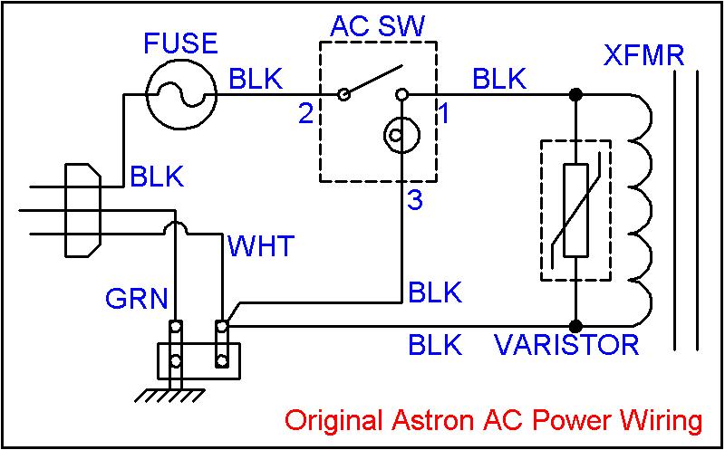
Owners of large 500-watt and higher Astron linear power supplies, as well as large HF amplifiers, are familiar with the "GNNNNnng" sound that occurs upon power-up. This noise is caused by the high inrush (surge) current flowing into the...
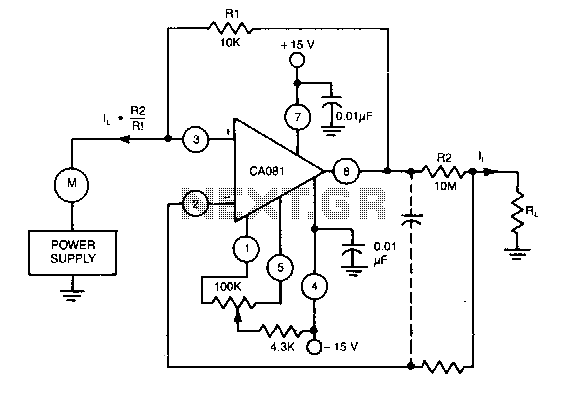
This circuit utilizes a CA018 BiMOS operational amplifier. A low current, supplied at the input potential as a power supply to the load resistor RL, is amplified by the resistor ratio R2/R1, while the load current h is monitored...
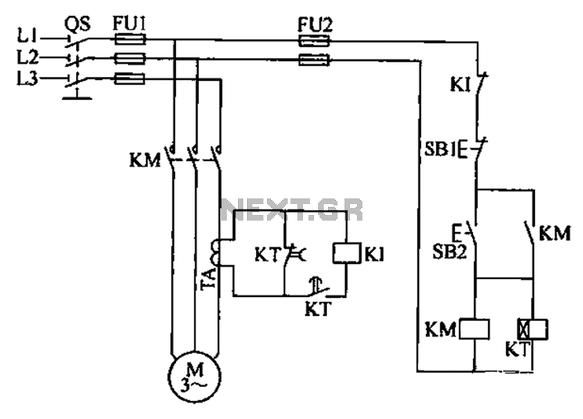
A three-phase electric motor overcurrent protection circuit. This example circuit utilizes a transformer to monitor the current, ensuring that the currents in the three-phase motor do not exceed normal operating levels. When the current exceeds the set threshold, the...
This LED (Light Emitting Diode) display consists of 10 LEDs to indicate the level of an input signal. If the signal is low, only LED #1 will light up. As the signal level increases, the illuminated dot will progress...