
MAX641 high current step-up converter

The MAX641 integrated circuit is a highly efficient solution for applications requiring a boost in voltage. The circuit operates by drawing power from a lower voltage source and converting it to a higher voltage output, making it ideal for battery-powered devices where voltage levels may drop as the battery discharges.
The step-up converter design involves a few key components: the MAX641 IC, input and output capacitors, and the resistors that form the voltage divider. The input capacitor is essential for stabilizing the input voltage and minimizing ripple, while the output capacitor helps smooth the output voltage and maintain a steady current supply.
The voltage divider consisting of resistors R1 and R2 is crucial for setting the low battery detection threshold. When the input voltage (LB1) falls below the reference voltage of 1.31 V, the output at LBO will switch to a low state, signaling that the battery voltage is critically low. This feature is particularly useful for preventing damage to the device from under-voltage conditions and ensuring proper functionality.
In practical applications, the circuit can be implemented on a printed circuit board (PCB) layout, ensuring that all components are placed in a manner that minimizes noise and interference. Proper grounding and decoupling techniques should be employed to enhance the performance of the step-up converter. The design can be further optimized by selecting appropriate values for R1 and R2 to adjust the threshold voltage according to specific requirements.
Overall, the MAX641 step-up converter circuit provides a reliable and efficient solution for applications where increased voltage is necessary while maintaining low power consumption and simple construction.Using MAX641 integrated circuit, manufactured by Maxim IC, can be designed a very simple step-up converter using few electronic components. This step-up high voltage converter electronic projects allows a maximum output current up to 1A. Low battery voltage detector input compare LB1 with internal reference of 1. 31 V. LBO output goes in low state when the voltage at pin 1 falls below 1. 31 V. The threshold voltage for "low battery", is determined by voltage divider R1-R2. 🔗 External reference
Related Circuits
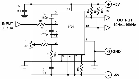
A voltage-to-frequency converter with a control range of 1:1000 can be constructed using the IC TSC9402. The specified component values in the circuit yield a conversion factor of 1 kHz per 1 V. Input voltages ranging from 10 mV...
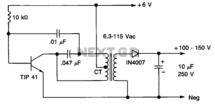
A 6 V battery can provide 100-150 Vdc center-tapped at a high internal impedance (not dangerous though it can inflict an unpleasant jolt). A 6.3 V transformer is connected in reverse with a transistor used in a Hartley oscillator...
My FM Wireless Microphone has been a very popular project with beginners and experienced constructors alike. It has been used inside guitars and as the basis of a remote control system. I do however, receive many requests for a...
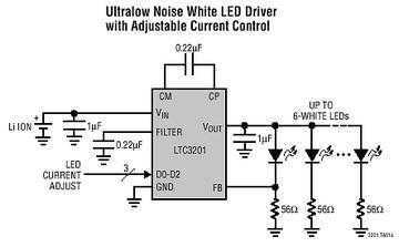
The LTC3201 contains overtemperature protection and can survive an indefinite output short to GND. Low external parts count (one small flying capacitor and three small bypass capacitors) and small MSOP-10 package size make the LTC3201 ideally suited for space...
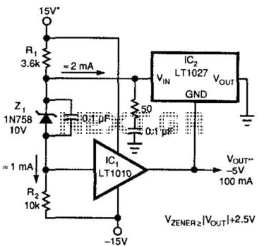
A method for enhancing the output current of a reference while also providing overload protection is illustrated. In this configuration, IC1 functions as a power buffer. The LT1027 regulates the output voltage (Vout) and ground to maintain a stable...
Additionally, it may be necessary to include another input capacitor to mitigate high-frequency noise, although this is not directly related to the main question. The objectives are to achieve a voltage output of 0 - 12 V with a...