
AC Motor Speed Controller Circuit

The triac-based motor speed controller circuit integrates a triac, a microcontroller, and passive components to modulate the speed of an AC motor. The triac serves as the primary switching device, controlling the power delivered to the motor by adjusting the phase angle of the AC waveform. The microcontroller governs the operation of the triac by generating the necessary trigger pulses based on the input from the potentiometer P1.
The self-stabilizing feature of the circuit ensures that the motor speed remains consistent under varying load conditions. This is achieved through feedback mechanisms that adjust the timing of the trigger pulse in response to changes in motor load, effectively compensating for any reduction in speed caused by increased resistance.
The circuit design requires careful attention to component specifications, particularly the triac and diac ratings, as well as the voltage and wattage ratings of the capacitors and resistors. The use of appropriate snubber capacitors is critical for protecting the triac from voltage spikes and ensuring reliable operation. The physical layout of the PCB must accurately reflect the schematic to prevent functional discrepancies and component failures.
In conclusion, the triac-based motor speed controller circuit is a versatile solution for controlling the speed of small AC motors, provided that the design is executed with precision and attention to detail in component selection and circuit layout.This triac-based 220V AC motor speed controller circuit is designed for controlling the speed of small household motors like drill machines. The speed of the motor can be controlled by changing the setting of P1. The setting of P1 determines the phase of the trigger pulse that fires the triac. The circuit incorporates a self-stabilizing technique that maintains the speed of the motor even when it is loaded. For example, when the motor of the drill machine is slowed down by the resistance of the drilled object, the counter-EMF of the motor also decreases. This results to a voltage increase in R2-P1 and C3 causing the triac to be triggered earlier and the speed increases accordingly.
Actually the circuit has errors. The layout of the board does not match the circuit (C1 should not be connected to the gate of the triac according to the diagram). Also, the group R1 C1 C2 does not seem to have any role, probably the node C1 C2 has to be connected somewhere else in the circuit.
I might use this circuit in my wife`s vacuum cleaner. Its speed control is drastically varying. The regulator uses a uC chip ST62T00C and a BTB16 600v triac. Nothing looks cooked` nor o/c nor s/c. The motor runs fines too. I`m about to try a BTB24 (24A) replacement. Maybe that`ll work. Using the circuit for a 1 amp 100 watt 1/8 HP universal motor I had to reduce C4 to. 022uF to get any sensible action. Then I dropped R3 to 33K, scrapped R2 and changed P1 to a value of 150K (well, I put a 470K in parallel with the original 220K var). This is a non-critical component, but 200uH seem unreasonably high. What I would do is to make a 50uH air core inductor by winding 54turns solid wire around a 1 ³ dowel.
Select wire size for load current. However I can say from my experience that there is no way it can handle 25A continuously probably contains a 25A TRIAC, but to keep it below the rated junction temperature, the case must be kept below 85 °C. With an on-state voltage of 1. 2V, P = 30W. This requires a heatsink rated at less than 2 °C/W. The best PCB heatsinks (much larger than this one) run at over 3 °C/W. The snubber /filter capacitors (C1 & C2) should be 600 to 660VAC polypropylene type for 220VAC, but this does not mean that other 400VDC film capacitors will not be reliable.
C3 & C4 may be low voltage film (100V). what are the values for triac and diac and what voltage rating for the capacitors and wattage rating for the resistors. thanks. gonna try this for a certain project. Hi i have made this project but i have a problem, at max speed the motor doesnt even move just buzzing what can cause this problem and please reply how to fix it sooner as posible.
Here is the parts i have installed: PS. the motor is from drill and it works perfectly and i have wondering about the inductor because in the project says 220 microHenrys and mine is 330 microHenrys it looks like theese the pcb does not match the schematic diagram. in the PCB, C1 should be disconnected from the gate instead connected to R2 and connected to the motor, making R2 and C1 parallel.
Also R1 should be connected to L1, C2 and the 220V AC line. 180 0hm resistor got burned when i connect this to a 250 v 5 amp ac motor . what counld have gone wrong plese give ur rplys as comments immedietly as i have a project to submit please The 180 © resistor should be 1/2W or greater carbon composition or wirewound so it can support the high transient voltage /current (peak power) that occur in the snubber circuit. My guess is that this is the issue I know from experience that carbon film generally cannot handle the peak power very short thermal time constant due to the very thin resistance element.
I built and tried the pcb circuit. The motor run like a newly ridden horse. There were also some sparks in the wire inside the motor. After that the pcb circuit is no longer functioning. But the motor is is still ok when I plugged it directly in the 220 AC lin 🔗 External reference
Related Circuits
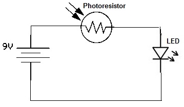
A simple photoresistor circuit will be constructed to demonstrate the operation of a photoresistor, which activates the circuit in the presence of light and deactivates it in darkness. This circuit connects a photoresistor to an LED. When the photoresistor...

This circuit is designed to secure a vehicle at a low cost if constructed independently, making it more affordable than purchasing a commercial car alarm system. The alarm is activated by opening switch Sw1, which can be any small...
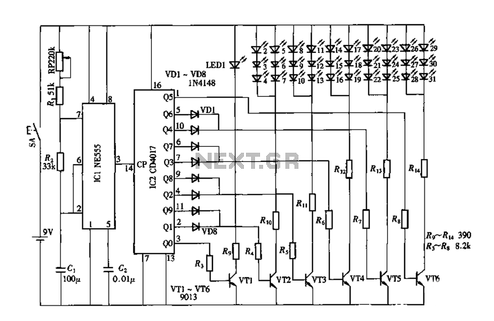
An electronic decorative peacock consists of 10 light-emitting diodes (LEDs), each of which contains multiple LEDs arranged in the tail of the peacock model. The light emission drive circuit operates the fan-shaped LEDs in a cyclic manner, emitting light...
One cannot expect high performance from a basic detector-based meter. Its sensitivity is merely sufficient to provide a fundamental understanding of the power output that the transmitter can achieve. The detector-based meter operates on a straightforward principle where it measures...
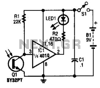
The IR Tester circuit indicates whether the button pressed on a remote control is functioning. Q1 is a phototransistor that is activated by infrared (IR) energy. The IR Tester circuit operates by detecting infrared signals emitted by remote control devices...
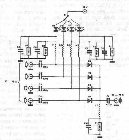
This antenna selector circuit diagram utilizes PIN diodes, which address the drawbacks of mechanical switches, particularly in high-frequency current applications. PIN diodes are well-suited for this purpose due to their linear resistance characteristics across a wide range of current...