
Antenna selector circuit diagram using PIN diodes

This antenna selector circuit effectively utilizes PIN diodes to provide a reliable and efficient means of switching between antennas without the mechanical wear and limitations associated with traditional switches. The linear resistance of the PIN diodes allows for precise control over signal modulation, which is critical in high-frequency applications where signal integrity is paramount. The inclusion of capacitors C1, C4, and C9 serves to isolate the DC components from the RF signals, ensuring that only the intended high-frequency signals are processed, thereby enhancing the overall performance of the circuit.
Inductors L1 and L5 play a crucial role in maintaining signal quality by preventing unwanted leakage currents that could distort the high-frequency signals. The design of these inductors on a ferrite core enhances their inductive properties, making them effective at the frequencies of interest. The choice of using enameled copper wire of a specific gauge (0.3 mm) and the precise number of turns (two) are optimized for the desired inductance values needed for both VHF and UHF bands, ensuring that the circuit maintains the necessary impedance matching for optimal signal transfer.
Resistors R2 and R5 are strategically placed to ground the unused diode anodes, which is essential for preventing cross-talk between different antenna signals. This design consideration is critical for applications where multiple antennas may be used simultaneously, as it ensures that only the selected antenna's signal is processed, thereby avoiding interference and maintaining signal clarity.
Overall, this antenna selector circuit is a sophisticated solution for managing multiple antennas in high-frequency applications, providing flexibility and reliability while maintaining signal integrity through careful component selection and circuit design.This antenna selector circuit diagram uses PIN diodes which eliminate disadvantages of mechanical switches (especially at high frequency current) PIN diodes can be used which are ideal for this purpose. Resistance diodes such changes linearly in a wide range of current values. This feature is ideal for a number of applications: by changing the cur rent-biased, the PIN diode can be used for mitigation, equalization or amplitude modulation of high frequency signals. Capacitors C1. C4 and C9 are used for preventing the entry and exit DC circuit. L1 shock. L5 prevent leakage to the table, the bar food, the HF signal. Resistances R2. R5 ensure that their unused diode anodes to be connected to ground, so that it is impossible to mix different antenna signals.
L1 shock. L5 can be wound on a ferrite core, using enamelled copper wire of 0. 3 mm diameter, two turns will be enough entries for the VHF UHF and 5 (1 uH is required for UHF and VHF about 5 uH). The circuit was designed for antennas with input impedance of 50. 75 ohms. 🔗 External reference
Related Circuits
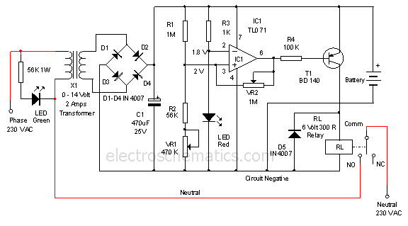
This is a 12-volt lead-acid automatic battery charger that stops the charging process once the battery reaches a full charge. This feature prevents overcharging. The 12-volt lead-acid automatic battery charger is designed to efficiently charge lead-acid batteries while ensuring safety...
Some good inverter circuits I found oscillate at approximately 50 to 60 Hz. They are likely capable of handling up to two amps; any more than that will cause them to automatically shut off. If there are questions, please...
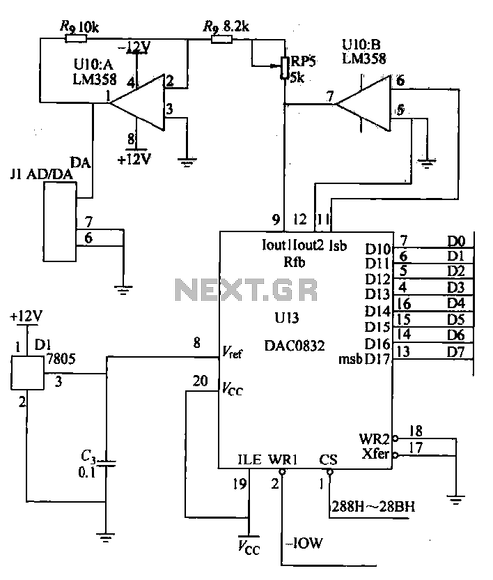
A digital-to-analog (D/A) conversion circuit utilizing the DAC0832 and the operational amplifier LM358, featuring two output channels with unipolar voltage output. The digital input range is from 00H to FFH, which corresponds to an output voltage range of 0V...
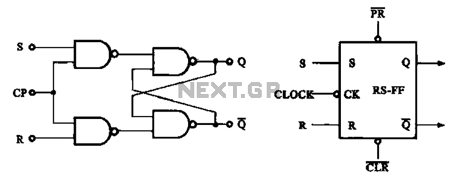
The asynchronous RS flip-flop mentioned earlier is not synchronized with the system clock signal. In contrast, the synchronous RS flip-flop incorporates synchronization, allowing it to operate in conjunction with the clock signal. Figure (a) illustrates the circuit configuration of...
The adjustable voltage monitor can be used to check whether the voltage in a circuit remains within a given range. If the DC voltage is less than the voltage at pin 5 of U1-B, then LED1 will light. If...
The 10-meter 27MHz continuous wave (CW) radio amplifier is equipped with the VN66AF transistor produced by Siliconix, which offers several advantages: it is inexpensive, provides excellent dielectric insulation, and has high gain. The VN66AF is utilized as an RF...