
IR Remote Control Extender circuit diagrams

The IR1 module (IC3) operates on a 5-volt DC supply, which is provided by the 7805 voltage regulator (IC1). Under quiescent conditions, without any IR signal, the output pin maintains a high voltage of approximately 5 volts DC. This output needs to be inverted and buffered for driving the IR phototransmitter LED (LED2). The buffering is achieved using one gate (pins 2 & 3) of a hex inverter, the CMOS 4049 (IC2). Although the IR1 module can directly drive TTL logic, a pull-up resistor (R4) is necessary for interfacing with CMOS ICs. This resistor guarantees that the signal from the remote control oscillates between 0 and 5 volts. Given that TTL logic levels differ slightly from CMOS, the 3.3k resistor (R4) is connected to the +5 volt supply line, ensuring that the logic high signal remains at 5 volts rather than the TTL level of 3.3 volts. While this resistor does not impact the performance of the IR module, it ensures stable operation when driving the CMOS buffer.
The output from pin 2 of the 4049 directly drives transistor Q1, with a 10k resistor (R1) limiting the base current. LED1, a red LED, flickers to indicate the reception of a signal from a remote control. It is noteworthy that in this circuit, the carrier signal is still present, albeit at a reduced level, alongside the decoded IR signal. The CMOS 4049 and BC109C transistor amplify both the carrier and the signal, driving LED2 at a peak current of approximately 120 mA when a signal is detected. Measurement with a digital multimeter may yield a lower reading, typically around 30 mA, as the meter captures the average DC value rather than the peak current. Devices designed to operate within the 36 to 40 kHz range should function effectively with this circuit, although controls operating at frequencies outside this range may experience reduced operational range. An exception to this compatibility is noted with some satellite receivers that utilize IR controls modulated at approximately 115 kHz, which are currently not supported by this circuit. Future iterations, such as a Mark 3 version, are being developed to address this limitation by reintroducing the carrier signal.This is an improved IR remote control extender circuit. It has high noise immunity, is resistant to ambient and reflected light and has an increased range from remote control to the extender circuit of about 7 meters. It should work with any domestic apparatus that use 36-38kHz for the IR carrier frequency. Please note that this is NOT compatible with some satellite receivers that use 115KHz as a carrier frequency. The main difference between this version and the previous circuit, is that this design uses a commercially available Infra Red module. This module, part number IR1 is available from Harrison Electronics in the UK. The IR module contains a built in photo diode, amplifier circuit and buffer and decoder. It is centerd on the common 38kHz carrier frequency that most IR controls use. The module removes most of the carrier allowing decoded pulses to pass to the appliance. Domestic TV`s and VCR`s use extra filtering is used to completely remove the carrier. The IR1 is packaged in a small aluminium case, the connections viewed from underneath are shown below: The IR1 module (IC3) operates on 5 Volt dc.
This is provided by the 7805 voltage regulator, IC1. Under quiescent (no IR signal) conditions the voltage on the output pin is high, around 5 volts dc. This needs to be inverted and buffered to drive the IR photo emitter LED, LED2. The buffering is provided by one gate (pins 2 & 3) of a hex invertor the CMOS 4049, IC2. The IR1 module can directly drive TTL logic, but a pull-up resistor, R4 is required to interface to CMOS IC`s. This resistor ensures that the signal from a remote control will alternate between 0 and 5 volts. As TTL logic levels are slightly different from CMOS, the 3. 3k resistor R4 is wired to the +5 volt supply line ensuring that the logic high signal will be 5 volts and not the TTL levels 3.
3 volts. The resistor does not affect performance of the IR module, but DOES ensure that the module will correctly drive the CMOS buffer without instability. The output from the 4049 pin 2 directly drives transistor Q1, the 10k resistor R1 limiting base current.
LED1 is a RED LED, it will flicker to indicate when a signal from a remote control is received. Note that in this circuit, the carrier is still present, but at a reduced level, as well as the decoded IR signal. The CMOS 4049 and BC109C transistor will amplify both carrier and signal driving LED2 at a peak current of about 120 mA when a signal is received.
If you try to measure this with a digital meter, it will read much less, probably around 30mA as the meter will measure the average DC value, not the peak current. Any equipment designed to work between 36 and 40kHz should work, any controls with carrier frequencies outside this limit will have reduced range, but should work.
The exception here is that some satellite receivers have IR controls that use a higher modulated carrier of around 115KHz. At present, these DO NOT work with my circuit, however I am working on a Mark 3 version to re-introduce the carrier.
🔗 External reference
Related Circuits
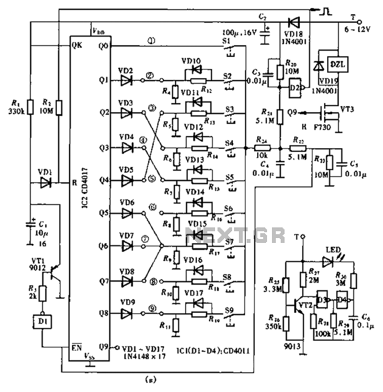
The lock circuit utilizes a decimal counter CD4017, which consists of ten output terminals. These terminals are connected through a combination that corresponds to a group of passwords, allowing for a maximum of up to 100 million combinations, hence...
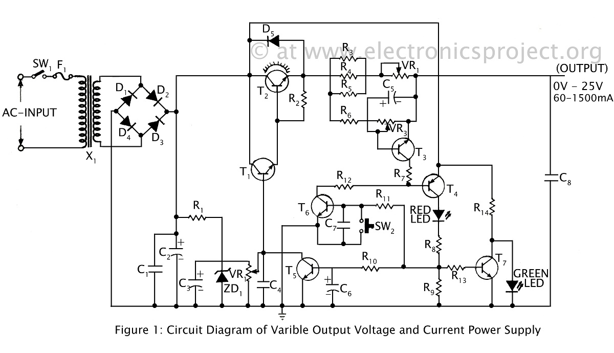
A ripple-free, short-circuit protected variable output voltage and current power supply is presented on this website as a verified project. The circuit diagram includes a description of various power supply circuits. This power supply circuit is designed to provide a...
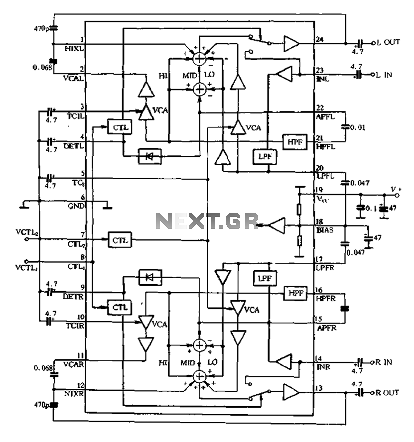
The BA3884 operates with a DC voltage range of 5.4 to 12.3V. Its internal circuit design and application circuit are represented in Figure 5-16. This circuit consists of a dual-channel processing system, which processes audio signals through two identical...
Obtain more information about the circuit diagram of a mobile jammer by visiting this link. A GSM jammer, or cell phone jammer, is a device that transmits signals on the same frequency used by the GSM system. The effectiveness...
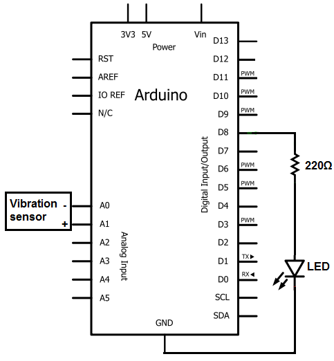
The sensors consist of a thin strip of piezoelectric material with a rivet at one end acting as a weight. When vibration occurs, the weight moves, stressing the piezo material, which generates a spike in voltage that can reach...
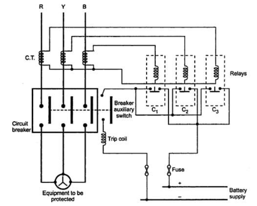
Consider a simplified circuit of a typical relay, which is usually part of a three-phase circuit with a complex contact system. The provided diagram illustrates a single-phase simplified circuit to clarify the basic operation of a relay. Part A...