
AC welder saving controller circuit diagram

The AC welder saving controller circuit is designed to optimize the operation of an AC welder by managing its power consumption effectively. The circuit typically consists of a microcontroller or a relay-based system that monitors the load conditions of the welder. When the welder is not in use—meaning there is no load detected—the circuit will disconnect the power supply, preventing unnecessary energy consumption.
Key components of this circuit may include:
1. **Microcontroller or Relay**: Acts as the central control unit that processes input signals from current sensors and makes decisions to cut off or restore power.
2. **Current Sensor**: This component continuously monitors the current flowing through the welder. If the current falls below a predefined threshold, indicating that the welder is not in use, the sensor sends a signal to the microcontroller to disconnect the power.
3. **Power Relay or Solid-State Relay (SSR)**: This component is responsible for physically disconnecting the power supply to the welder. It is controlled by the microcontroller based on the input from the current sensor.
4. **Power Supply Circuit**: This circuit provides the necessary voltage and current to the control components and ensures stable operation.
5. **User Interface (optional)**: Some designs may incorporate a user interface for settings adjustments, such as threshold levels for load detection or manual override options.
The operational flow begins when the welder is powered on. The current sensor detects the load and sends the information to the microcontroller. If welding activity is detected, the power remains connected. However, once the welding operation ceases, the current sensor identifies the drop in load, prompting the microcontroller to activate the relay and disconnect the power supply.
This automatic power management feature not only enhances the efficiency of the welder but also contributes to energy conservation, reducing operational costs and extending the lifespan of the equipment. The design can be further enhanced with additional features such as indicators for power status or integration with smart home systems for remote monitoring.AC welder is intermittent operation, the intermittent load power consumption during the period up to several hundred watts. AC welder saving controller circuit shown in Fig. Th is circuit allows the welding machine automatically cut off power at no load, but also automatically power welding, thereby saving.
Related Circuits
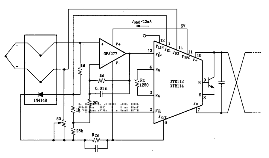
The OPA277 is configured as an inverting amplifier. This inverting amplifier utilizes high input impedance characteristics to minimize loop thermocouple offset drift. A 50-ohm potentiometer is included for calibration, allowing for the adjustment of the inverting input of the...
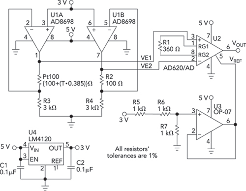
Bridge circuits are widely used for conditioning signals from resistive sensors. These circuits are sensitive to minor changes in resistance, providing a differential output from a single current or voltage source. However, the sensors connected to a passive bridge...
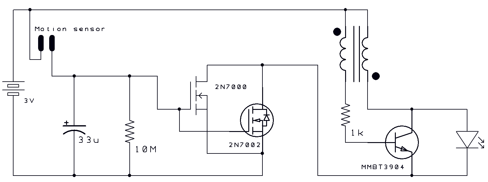
Two thoughts on a motion-activated Joule Thief LED bike light. The circuit for switching on and delayed switch-off is simple. The motion-activated Joule Thief LED bike light utilizes a straightforward circuit design that capitalizes on the principles of energy conservation...
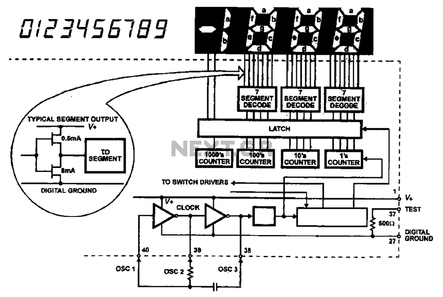
The AC input circuit functions as a converter, transforming an alternating current (AC) signal into a direct current (DC) signal, which is subsequently processed by an analog-to-digital (A/D) converter chip. The input circuit is designed to handle AC signals, typically...
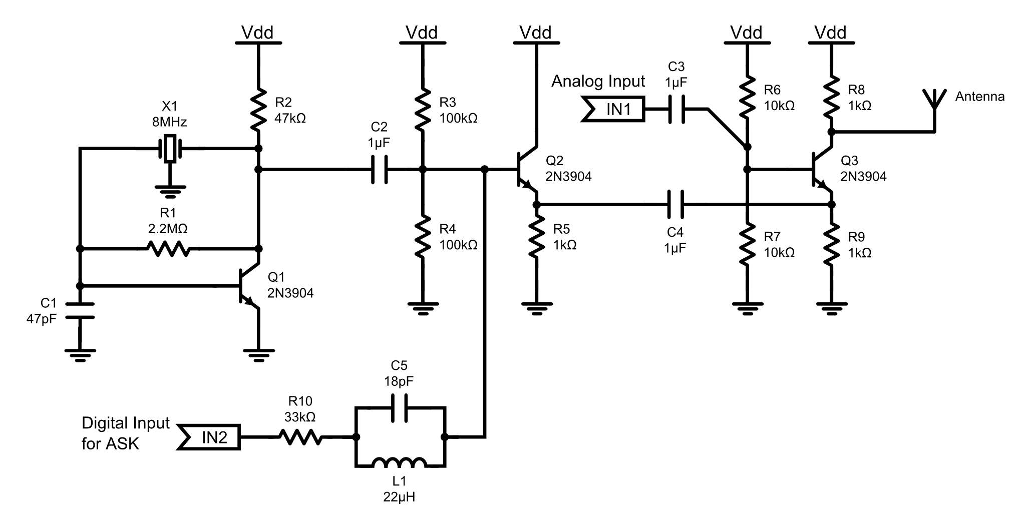
This is an 8MHz amplitude modulated (AM) radio transmitter designed primarily for practical applications and as an educational exercise in electronics. The objective was to create a simple radio transceiver that could be used in future projects requiring basic...
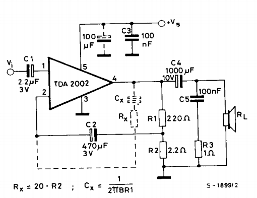
This is a power amplifier circuit built using the TDA2002 power amplifier IC module. It serves as a replacement for the original LM383, which is no longer available. The circuit is easy to assemble and requires a minimal number...