
ICL7107 chip digital circuit section 2

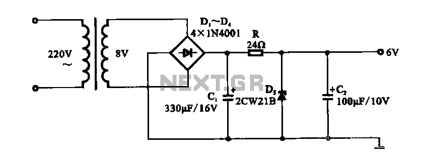
The input circuit is designed to handle AC signals, typically sourced from mains voltage or other alternating sources. The first stage of the circuit involves a rectifier, which converts the AC signal into a DC signal. This rectification can be achieved using a full-wave bridge rectifier configuration, which consists of four diodes arranged in a bridge layout. This configuration ensures that regardless of the polarity of the input AC signal, the output will always be a positive DC voltage.
Following the rectification process, a filtering stage is employed to smooth the pulsating DC output. This is typically done using capacitors, which charge during the peaks of the rectified signal and discharge during the troughs, effectively reducing the ripple voltage and providing a more stable DC output. Depending on the application, additional filtering stages, such as inductors or more capacitors, may be included to further enhance the quality of the DC signal.
Once the AC signal has been successfully converted and stabilized as a DC signal, it is fed into the A/D converter chip. The A/D converter is responsible for sampling the DC voltage at specific intervals and converting it into a digital representation, which can then be processed by a microcontroller or other digital circuitry. The resolution and sampling rate of the A/D converter will determine the accuracy and responsiveness of the digital output.
In summary, the circuit effectively transforms an AC input into a clean and stable DC signal suitable for digital processing, ensuring accurate measurements and reliable performance in various electronic applications.AC has been shown as a fishing converter input circuit ND conversion Tiger Road. In order to check the AC signal and I was shown, it is provided in the input circuit AC DC conv erter circuit, the first AC signal into a DC signal, and then into the A/D converter chip.
Related Circuits
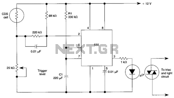
This circuit can control the on/off cycle of a light using a CDS photocell and turn it off after a preset period. The light can only be activated when the CDS cell is in darkness, and it remains on...

This circuit is designed to detect the approximate percentage of salt contained in a liquid. After careful calibration, it provides a quick, rough indication of the salt content in liquid foods for dietary purposes. The circuit utilizes the LM324...
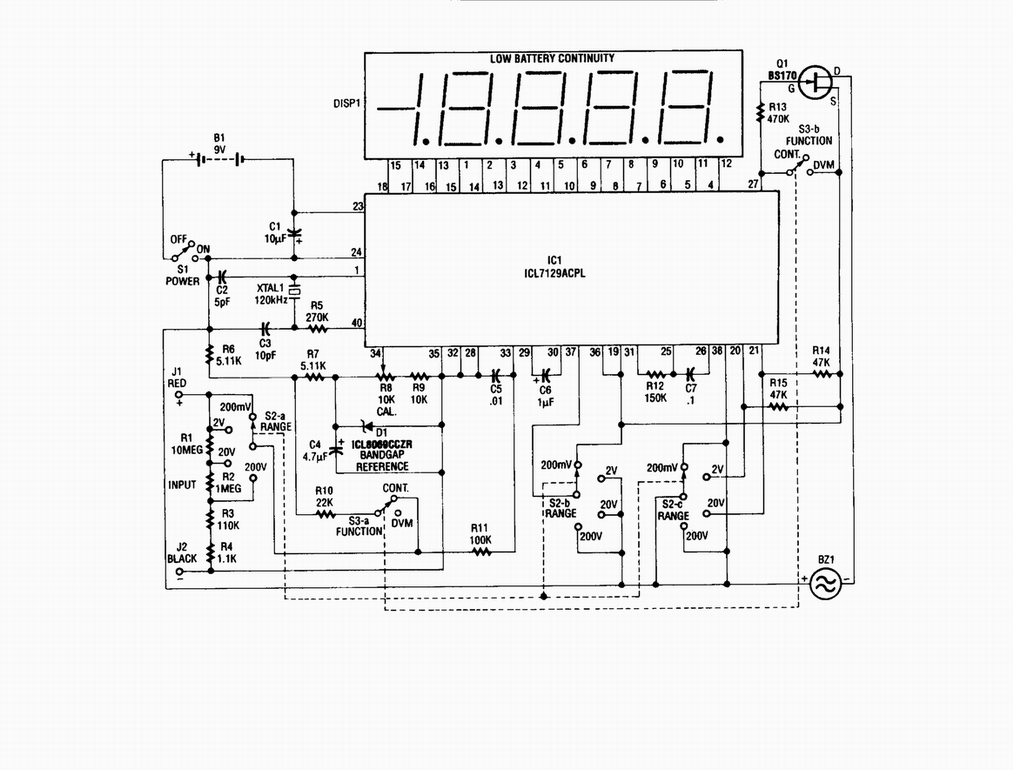
Single-chip digital voltmeter. This 4 1/2-digit DVM circuit is built around a Maxim ICL7129ACPL A/D converter and LCD driver. An ICL8069 CCZR 1.2-V band-gap reference diode is used for accuracy. The described circuit is a single-chip digital voltmeter (DVM) utilizing...
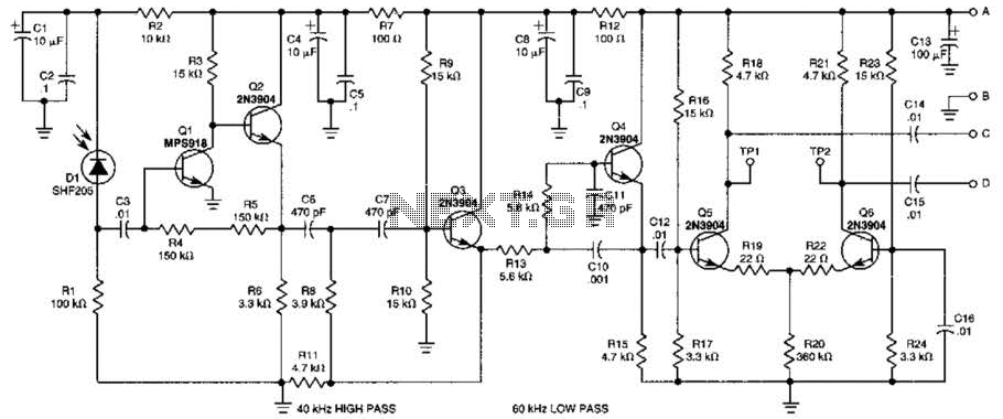
This receiver is designed to detect infrared (IR) or light beams that are frequency modulated on a 50-kHz carrier. The transistors Q2, Q1, Q3, and Q4 form an active filter and amplifier, while the differential amplifier formed by Q5...
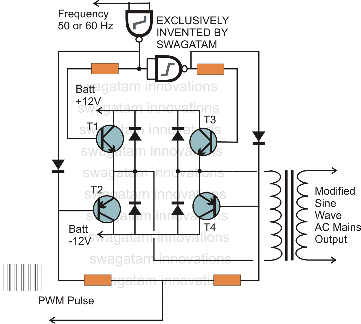
In electronics, an H-bridge circuit refers to a configuration consisting of four individual switching devices, such as transistors or MOSFETs, which can be controlled by external discrete signals from the respective stages of the control circuit. During operation, the...
A DC shunt regulator power supply circuit is presented, which operates in parallel with a radio circuit. The circuit begins with an AC voltage of 22V, which is stepped down to 8V using a transformer. The 8V AC voltage...