
8MHz AM radio transmitter circuit

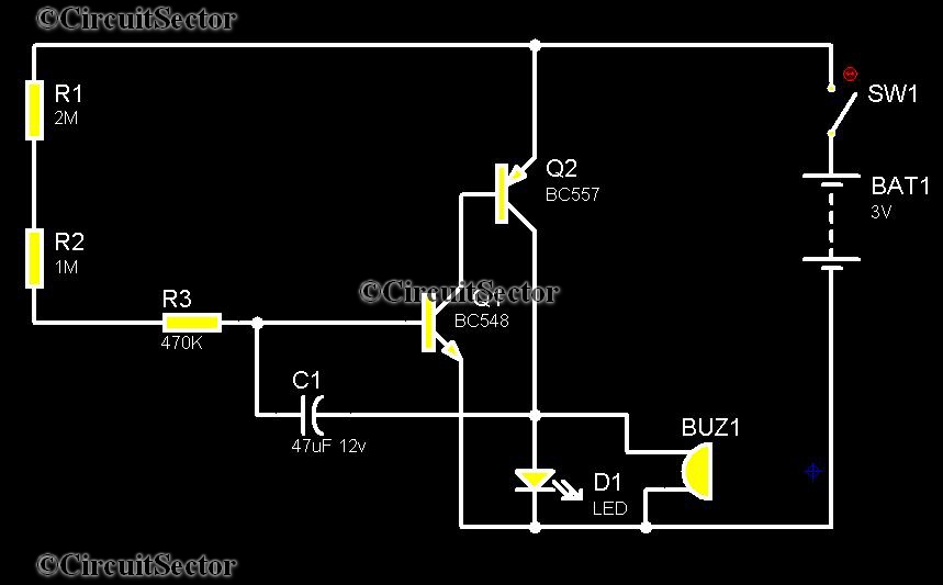
The circuit is divided into three main components: the oscillator, the buffer, and the mixer. It operates on a power supply voltage of 3.3V. The oscillator generates the 8MHz carrier signal and is implemented as a minimalist single-transistor (Q1) Pierce oscillator, based on the design outlined in National Semiconductor Application Note 400 (AN400 – A study of the crystal oscillator for CMOS-COPS, Fig 6). The resonating element is an 8MHz ceramic resonator (X1) with integrated capacitances, supplemented by an additional capacitor (C1) to ensure proper oscillation.
The buffer serves to isolate the oscillator from the loading effects of the mixer, utilizing a standard emitter follower configuration with transistor Q2. Direct connection of the oscillator to the mixer would compromise its functionality, which is why the buffer is a critical component of the design. The possibility of removing the buffer by increasing the input impedance of the mixer was not explored.
This AM radio transmitter circuit exemplifies fundamental principles of RF design and serves as a practical tool for both educational and experimental purposes. The choice of components, such as the ceramic resonator and transistors, reflects a balance between performance and accessibility, making it suitable for both novice and experienced electronics enthusiasts. The circuit's simplicity allows for easy troubleshooting and modifications, which can further enhance the learning experience for students and hobbyists alike. The design can also be expanded or adapted for various applications, including signal processing and communication experiments.This is an 8MHz amplitude modulated (AM) radio transmitter, which I built mainly for work, and also as an exercise in electronics (it is the first RF transmitter I’ve ever built). We wanted to have a simple radio transceiver design at our disposal for some possible projects in the future that might require a primitive means of short range wireless communications.
Also considered was the possibility of getting kids to build this as part of the courses we teach in secondary schools. The buffered carrier signal goes to the mixer circuit, where its amplitude gets modulated by the analog signal input from IN1.
This is just a common-emitter ‘amplifier’ with the transistor (Q3) biased close to / in the saturation region which is necessary for the whole thing to work as a mixer. The output of the mixer connects directly to the antenna, which is nothing more than a rather long (>30cm) length of wire.
The circuit consists of 3 parts: oscillator, buffer, and mixer. It runs on a power supply voltage of 3.3V. The oscillator produces the 8MHz carrier signal. It is a minimalist single-transistor (Q1) Pierce oscillator, and the design comes from National Semiconductor Application Note 400 (AN400 – A study of the crystal oscillator for CMOS-COPS, Fig 6). The resonating element is an 8MHz ceramic resonator (X1) with built-in capacitances (we have quite a few lying around in the office).
An additional capacitance C1 is necessary to get the circuit to oscillate properly. The buffer isolates the oscillator from loading by the mixer. It is a standard emitter follower circuit using Q2. The oscillator will not work properly if connected directly to the mixer. I did not explore the possibility of eliminating the buffer by increasing the input impedance of the mixer. 🔗 External reference
Related Circuits
Telephones are declining globally; however, India has over 350 million mobile phone users, alongside a significant number of traditional telephone users. This telephone timer is designed to save costs by controlling unnecessary time spent during phone calls. This simple...
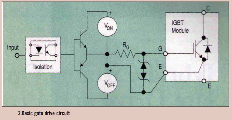
High power IGBT modules utilize hybrid integrated circuit (IC) gate drives that incorporate protection circuits, which implement desaturation detection or real-time control. High power Insulated Gate Bipolar Transistor (IGBT) modules are essential components in various high-efficiency power conversion applications, such...

This light-sensitive automatic light switch circuit is designed to be connected to the main 220V supply. The circuit will activate a 220V lamp during nighttime. The light-sensitive automatic light switch circuit operates by utilizing a light-dependent resistor (LDR) to detect...

This topic will be locked and will display all of the circuits and some photos of the devices being worked on in the Joule Thief topic. This process will take some time, so patience is appreciated. If any errors...
This integrated circuit (IC) requires fewer external components, making it simpler for beginners to assemble it on a veroboard. The original circuit was sourced from its datasheet. A slightly modified version of the circuit is presented below. This circuit...
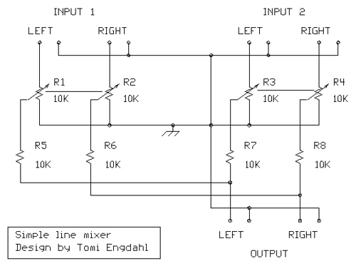
The mixer circuit described features three line inputs and three microphone inputs. The microphone inputs are designed for low impedance dynamic microphones with a range of 200 to 1000 ohms. Alternatively, an electret condenser microphone (ECM) can be used,...