
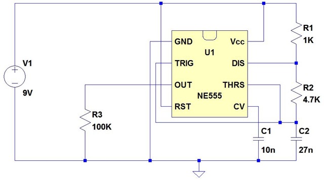
ac What is the output voltage of this 555 timer high voltage circuit

The transformer in question operates on the principle of electromagnetic induction, where an alternating current (AC) in the primary coil generates a magnetic field that induces a voltage in the secondary coil. The transformation ratio, defined as the ratio of the number of turns in the primary coil to the number of turns in the secondary coil, plays a crucial role in determining the output voltage.
In this scenario, the transformer has a turns ratio of 125:1, which implies that for every 1 turn in the primary winding, there are 125 turns in the secondary winding. This results in an output voltage that is significantly higher than the input voltage. The calculation of the output voltage can be expressed using the formula:
\[ V_{out} = V_{in} \times \left( \frac{N_{secondary}}{N_{primary}} \right) \]
Where:
- \( V_{out} \) is the output voltage,
- \( V_{in} \) is the input voltage (12V in this case),
- \( N_{secondary} \) is the number of turns in the secondary coil,
- \( N_{primary} \) is the number of turns in the primary coil.
Substituting the known values into the formula yields:
\[ V_{out} = 12V \times 125 = 1500V \]
This output voltage is theoretically correct under ideal conditions, assuming there are no losses due to resistance in the windings or core losses. However, practical transformers may exhibit losses that could affect the actual output voltage. Factors such as the efficiency of the transformer, load conditions, and frequency of operation can also influence the final output voltage. Therefore, while the calculated output is 1500V, it is advisable to verify this with measurements under actual operating conditions to ensure accuracy.Calculated the output of the transformer to be 125 times (1000 / 8) higher than input. Since 12v is given as input, output should be 1500v (not sure about this) 🔗 External reference
Related Circuits
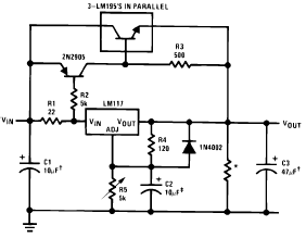
The following circuit diagram illustrates the application of the LM117 as a high current adjustable regulator. The LM117 is capable of supplying more than 1.5A. The LM117 is a popular adjustable voltage regulator that is designed to provide a stable...
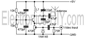
The video transmissions from this unit can be received on a small portable, tunable, and battery-operated TV set, similar to those found in flea markets. The described unit is capable of transmitting video signals that can be captured by compact,...
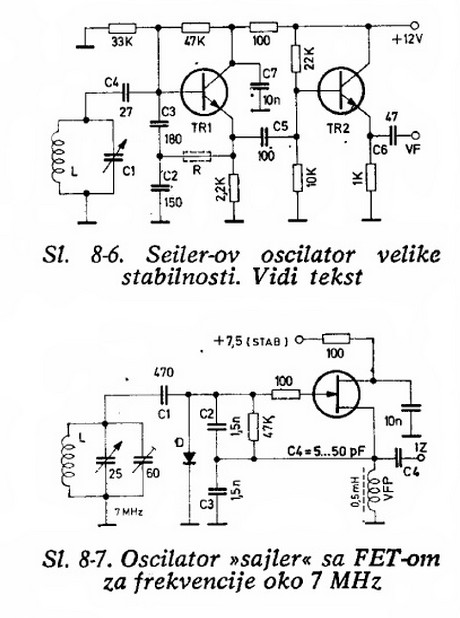
Will an LC-based oscillator be able to demonstrate performance comparable to crystals under such conditions (possibly in unusual configurations like LC-opamp) so that any energy loss at each stage is recovered, resulting in a narrower bandwidth? Examine some amateur...
The issue began when a girlfriend expressed her frustration with mosquitoes disrupting her nights. It was recognized that mosquito sprays provide only temporary relief, as the insects tend to return after some time. A suggestion was made for an...
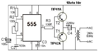
This 12V power inverter circuit can be utilized to power small devices that require 240 volts. It is particularly advantageous for operating 240-volt appliances using a 12-volt car battery. Unlike typical feedback oscillator inverters, this design employs a 555...
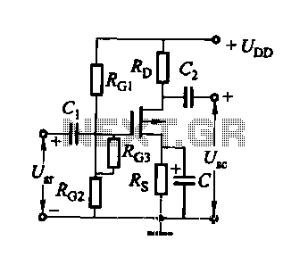
FET several basic bias circuit - self-bias voltage divider circuit The self-bias voltage divider circuit is a fundamental configuration used in Field Effect Transistor (FET) biasing. This circuit employs two resistors to create a stable bias voltage for the transistor's...