
Acoustic Sound Transmitter

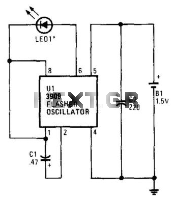
The circuit described produces pulsed sound through the operation of a bistable multivibrator and a piezo transducer. The primary component, U1, functions as a bistable multivibrator, which is essential for ensuring stable transitions between two states. This characteristic is particularly useful in debouncing a mechanical switch, denoted as S1. When the switch is activated, it may produce multiple unwanted transitions due to mechanical bounce. The bistable multivibrator effectively filters these bounces, providing a clean output signal.
The capacitor C1 plays a crucial role in the timing aspect of the circuit. It is connected to the output of U1 and is responsible for generating a trigger pulse that is sent to U2. U2 is likely configured as a monostable multivibrator or a similar pulse-generating circuit, which receives the trigger from C1 and produces a defined output pulse. This output pulse is then directed to SPKR1, which is identified as a piezo transducer. The piezo transducer converts the electrical pulse into audible sound.
The design specifies a pulse width of 110 µs, which indicates the duration of the output signal generated by U2. This pulse width is critical as it determines the characteristics of the sound produced by the piezo transducer. A pulse width of 110 µs typically results in a short, sharp sound, suitable for applications such as alarms, indicators, or notifications.
In summary, this circuit effectively combines a bistable multivibrator for debouncing a switch, a timing capacitor for pulse generation, and a piezo transducer for sound output, resulting in a reliable and efficient pulsed sound generation system. Pulsed sound is produced by this circuit. Ul is used as a bistable multivibrator, which acts as a contact "debou ncer" for SI. CI feeds a trigger pulse to U2, which feeds a pulse to SPKR1, to piezo transducer. Values are shown for a pulse width of 110uS.
Related Circuits
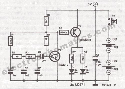
This infrared transmitter is designed for use with an infrared receiver. It operates using either two 1.5V batteries or a 3V lithium battery, allowing for a compact infrared communication system. The infrared transmitter circuit typically consists of an infrared LED,...
The flash rate of the IR diode is determined by the value of CI, a 220-µF capacitor that sets the oscillation rate at 1 Hz per second. Reducing CI will increase the frequency of the circuit, while larger values...
This small transmitter can reach distances of more than 1 km under favorable transmission conditions. Modulation can be achieved using a microphone, such as an electret microphone, or another audio source. The transmitter includes a coil made of 5...
This circuit is sourced from a remote control tarantula transmitter that operates at a frequency of 49.86 MHz. The schematic is also available on the FCC website by searching for the FCC ID. This device complies with Part 15.235...
This will probably be one of the last transmitters for the 88MHz to 108MHz band. This particular TX is of special interest to those wishing to build low power Power Amplifiers for the VHF bands since it used impedance...
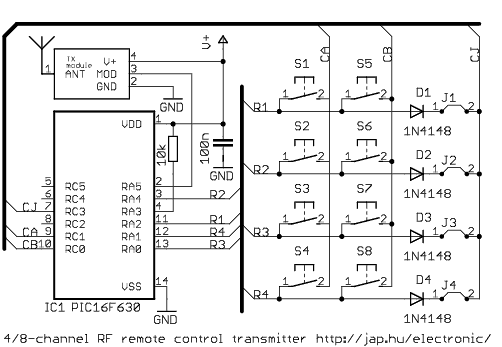
This is a general purpose remote control project with using programmable PIC microcontrollers. Schematics are shown for using infrared (RF) or radio (RF) media. If you are not familiar with microcontroller programming, you can use fixed encoder and decoder...