
Basic Infrared IR Transmitter Circuit

The infrared transmitter circuit typically consists of an infrared LED, a resistor, and a power source. The infrared LED emits light in the infrared spectrum, which is not visible to the human eye but can be detected by an infrared receiver. The choice of power source, either two 1.5V batteries in series or a single 3V lithium battery, provides flexibility in terms of size and capacity.
In the circuit, the infrared LED is connected in series with a current-limiting resistor to prevent excessive current flow that could damage the LED. The value of the resistor is determined based on the forward voltage and current specifications of the LED, as well as the voltage supplied by the batteries. For example, if the forward voltage of the infrared LED is 1.2V and the desired forward current is 20mA, the resistor value can be calculated using Ohm's law.
The transmitter may also include a modulation circuit to encode data onto the infrared signal, allowing for more robust communication. This can be achieved using a simple microcontroller or a timer IC that generates a square wave signal, which modulates the infrared LED's emission. The modulation frequency should be chosen based on the specifications of the corresponding infrared receiver to ensure optimal performance.
Overall, the infrared transmitter circuit is a vital component in remote control systems, wireless data transmission, and various applications requiring short-range communication. Its simplicity and effectiveness make it a popular choice for hobbyists and professionals alike.This infrared tranmitter is intended for use with this infrared receiver. It works with 2 - 1.5V batteries or a 3V lithium battery. To give a compact infra.. 🔗 External reference
Related Circuits
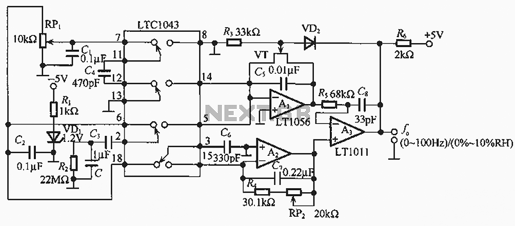
The humidity/frequency conversion circuit operates similarly to the previously mentioned humidity sensors. At a humidity level of 76%, the equivalent capacitance is 500 pF, with a capacitive relative humidity variation rate of +1.7 pF/%. The circuit includes an integrating...
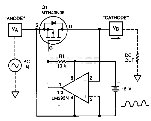
A TMOS power FET, Q1, and an LM393 comparator provide a high-efficiency rectifier circuit. When voltage V1 exceeds V2, the output of U1 becomes high, and Q1 conducts. Conversely, when V2 exceeds V1, the comparator output becomes low, and...
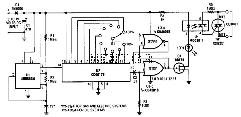
A timer (LM555CN) and decode counter are utilized to generate duty cycles ranging from 10% to 100% for controlling the operational time of a heating system. V2 operates as a decode counter that can be adjusted for duty cycles...
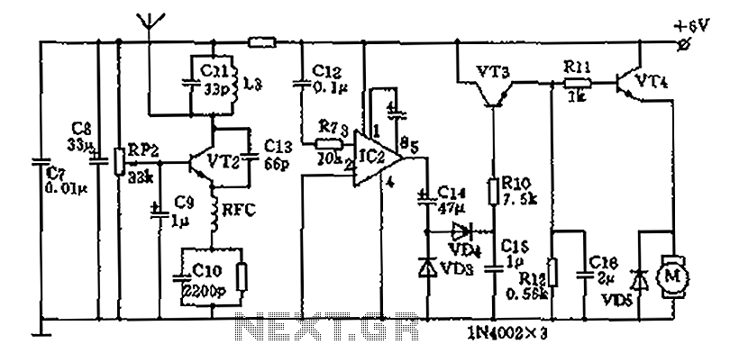
The homemade wireless remote control circuit diagram illustrates a motor remote control transmitter circuit. The circuit utilizes a 555 timer along with resistors R1, R2, RP1, diodes VD1, VD2, and capacitor C1 to create a variable duty cycle astable...
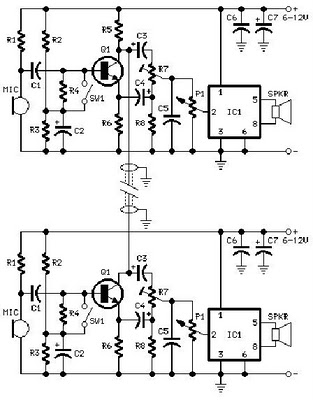
A project is proposed to construct a two-phone intercom system capable of functioning over a distance of up to 1 kilometer. The system will utilize the speaker of each phone to produce a ringing sound on the other end. The...
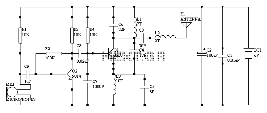
1000 m single-tube FM transmitter circuit diagram of oscillation. The circuit diagram for a 1000 m single-tube FM transmitter is designed to generate frequency modulation signals suitable for transmission over a distance of approximately 1000 meters. This transmitter employs...