
Across The Track Infrared Detectors

The infrared "Across The Track" train detection circuit utilizes the LM339 comparator as its core component, which is a quad comparator capable of comparing multiple voltage levels. This circuit is particularly effective in detecting trains as they pass through a designated area, employing infrared emitter and detector pairs that work in tandem to create an invisible barrier.
In a typical configuration, the infrared emitter transmits a continuous beam of infrared light, which is received by the infrared detector positioned directly opposite. When a train enters the detection zone, it interrupts the infrared beam, causing a change in voltage at the output of the detector. This change is then fed into one of the LM339 comparator inputs.
The LM339 is configured with a reference voltage at another input, which sets the threshold for detection. When the voltage from the detector drops below this reference level, the LM339 outputs a low signal, which can be used to trigger an alarm, activate lights, or interface with other control systems.
The circuit can be adjusted for various distances between the emitter and detector. While the basic design has been tested effectively with gaps up to 12 inches, it is recommended to maintain a practical distance of 8 inches or less for optimal performance and reliability. Additionally, the choice of matched infrared emitter and detector pairs is crucial, as their characteristics will influence the sensitivity and response time of the circuit.
In terms of power supply, the LM339 operates on a wide voltage range, typically from 2V to 36V, allowing for flexibility in deployment. Proper decoupling capacitors should be placed close to the power pins of the LM339 to minimize noise and ensure stable operation.
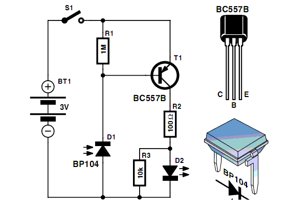
Overall, the infrared "Across The Track" train detection circuit offers a reliable and efficient solution for monitoring train movements, enhancing safety and operational awareness in rail systems.This page presents information on infrared - `Across The Track` train detection circuits. The circuits are designed around the LM339 comparator chip and can use a wide assortment of matched infrared - emitter / detector pairs. The basic circuit shown below has been tested with sensor gaps as wide as 12 inches but a distance of 8 inches or less is more practical.
🔗 External reference
Related Circuits
Men, in particular, appreciate the convenience of television remote controls, which can often lead to frustration for their female partners. Men seem to have a desire to understand what... The initial statement highlights a common dynamic in household technology usage,...
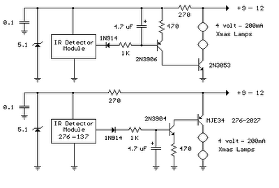
The infrared detector module (GP1U52X) (Radio Shack 276-137) generates a 5-volt TTL pulse train that corresponds to the digital code from a remote control button. In the circuit diagram, the module's output is normally low, producing a positive pulse...
While developing an infrared (IR) extender circuit, a method was needed to measure the relative intensities of various infrared light sources. This circuit is the outcome of that research. A photodiode, specifically the SFH2030, is utilized as the infrared...
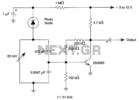
The circuit utilizes a tuned circuit for frequency selection, designed to operate at approximately 51 kHz. The 2N3565 transistor amplifies the output generated by the tuned circuit. The described circuit operates on the principle of resonance, where the tuned circuit...
Infrared remote control operates on 115 volts AC. This circuit enables the activation of any equipment that functions on 115 volts AC. The receiver circuit is based on the Radio Shack infrared system. The infrared remote control circuit designed for...
This circuit utilizes a 1458 dual operational amplifier (op-amp) to create a radar detector. Capacitor C1 serves as the radar signal detector. The first op-amp functions as a current-to-voltage converter, while the second op-amp buffers the output to drive...