
Economy radar detectors

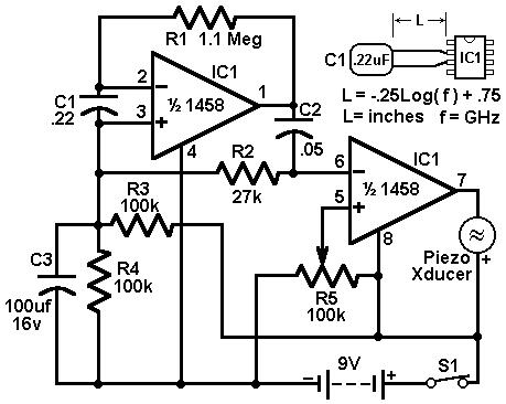
The described radar detector circuit employs a 1458 dual op-amp, which consists of two independent, high-gain, frequency-compensated op-amps. The design leverages the first op-amp to convert the radar signal detected by capacitor C1 into a voltage signal. This conversion is essential for accurately detecting the presence of radar signals. The output from the first op-amp is then fed into the second op-amp, which acts as a buffer. This buffering is crucial as it isolates the detection circuitry from the load imposed by the piezo transducer, ensuring that the op-amp operates within its optimal range and maintains signal integrity.
Resistor R5 plays a pivotal role in setting the threshold at which the second op-amp activates the piezo transducer. By adjusting R5, the sensitivity of the circuit can be fine-tuned to avoid false triggers from background noise, allowing the detector to respond only to significant radar signals. This adjustment is vital for practical applications, as it enhances the reliability of the radar detection.
The tuning of the circuit's response can also be influenced by the physical characteristics of capacitor C1. Specifically, the length of the leads connected to C1 can affect the circuit's sensitivity and response time. For optimal performance with typical road-radar systems, the recommended lead length of 0.5 to 0.6 inches is critical. This specification is based on empirical testing and ensures that the radar detector performs effectively in real-world scenarios.
Overall, this radar detector circuit exemplifies a balance of simple design and effective performance, making it suitable for various applications where radar detection is necessary.This circuit uses a 1458 dual op-amp to form a radar detector. C1 is the detector of the radar signal. The first op-amp forms a current-to-voltage converter and the second op-amp buffers the output to drive the piezo transducer. R5 sets the switching threshold of the second op-amp; normally it is adjusted so that the circuit barely triggers on bac
kground noise, then it`s backed off a bit. The response of the circuit may be tuned by adjusting the length of the leads on C1. For typical road-radar systems, the input capacitor`s leads should be about 0. 5 to 0. 6 inches long. 🔗 External reference
Related Circuits

An article discusses a do-it-yourself radar system constructed using the PIC18F452 microcontroller. This project is suitable for hobbyists, although the schematic details are not provided. The do-it-yourself radar system utilizing the PIC18F452 microcontroller presents an engaging project for electronics enthusiasts....
This circuit utilizes a 1458 dual operational amplifier (op-amp) to create a radar detector. Capacitor C1 serves as the radar signal detector. The first op-amp operates as a current-to-voltage converter, while the second op-amp acts as a buffer to...
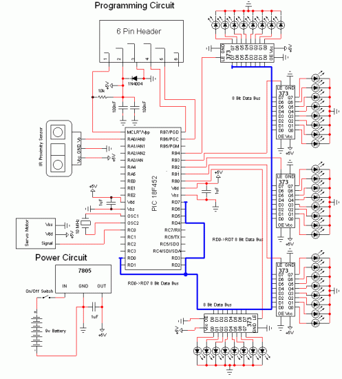
Chris from PyroElectro.com has an informative article detailing a do-it-yourself radar system constructed using the PIC18F452 microcontroller. This project is an excellent hobbyist endeavor, although the schematic design is quite complex. The system integrates three primary components to form...

This project presents a practical application in security and alarm systems for homes, shops, and vehicles. It consists of a set of ultrasonic receivers and transmitters operating at the same frequency. The design features an ultrasonic radar circuit. The...
This project has numerous practical applications in security and alarm systems for homes, shops, and vehicles. It features a set of ultrasonic transmitter and receiver operating at the same frequency. When an object moves within the area covered by...
The PTB78560x is a series of 30 W rated isolated DC/DC converters designed to operate from a standard 24 V or 48 V telecom central office (CO) supply. Housed in a 12 package, each model features a wide adjustable...