
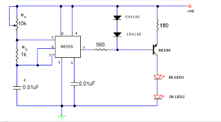
infrared remote control tester

The infrared extender circuit is designed to measure and compare the intensity of infrared light emitted from various remote controls. The core component, the SFH2030 photodiode, is sensitive to infrared wavelengths, making it suitable for detecting signals from remote control devices. When infrared light strikes the photodiode, it generates a small photocurrent proportional to the intensity of the light.
The CA3140 operational amplifier is configured in a differential mode to amplify the weak signals received from the photodiode. This configuration enhances the sensitivity of the circuit, allowing for accurate measurements of varying infrared light intensities. The output from the op-amp is then fed to a multimeter, which displays the voltage corresponding to the intensity of the infrared light. The relationship between the photocurrent and output voltage is linear, with approximately one volt produced for every microamp of current detected.
LED1 serves as a visual indicator, illuminating when infrared radiation is present, providing immediate feedback on the detection of IR signals. The choice of power supply is flexible; while a 12-volt power supply is recommended for optimal performance, a 9-volt battery can also be utilized, making the circuit versatile for different applications.
This circuit is particularly useful for testing remote controls, allowing users to determine the strength of the IR signals they emit. By aiming various remote controls at the photodiode from a fixed distance, users can effectively compare their performance based on the voltage readings from the multimeter. The circuit's design ensures that it is straightforward to assemble and use, making it an accessible tool for those interested in infrared technology and remote control diagnostics.As I was developing my IR Extender Circuit, I needed to find a way of measuring the relative intensities of different Infra red light sources. This circuit is the result of my research. I have used a photodiode, SFH2030 as an infra red sensor. A MOSFET opamp, CA3140 is used in the differential mode to amplify the pulses of current from the photodi
ode. LED1 is an ordinary coloured led which will light when IR radiation is being received. The output of the opamp, pin 6 may be connected to a multimeter set to read DC volts. Infra red remote control strengths can be compared by the meter reading, the higher the reading, the stronger the infra red light. I aimed different remote control at the sensor from about 1 meter away when comparing results. For every microamp of current through the photodiode, about 1 volt is produced at the output. A 741 or LF351 will not work in this circuit. Although I have used a 12 volt power supply, a 9 volt battery will also work here. 🔗 External reference
Related Circuits
A TV remote jammer circuit using the NE555 timer IC. This device allows users to watch their favorite TV channels without interruptions, as it prevents others from changing the channel using a remote control when the circuit is activated....
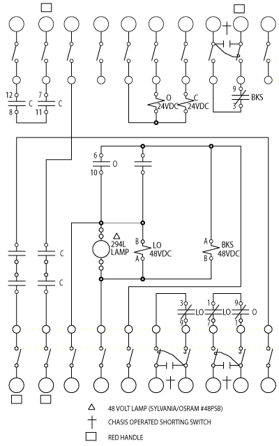
This SCADA controller is designed for use with distribution (13.2 kV/4.8 kV) substation transformer breaker positions where an automatic throw-over is present. The RTU voltage is 24V DC. The breaker status and lockout relays operate at 48V DC. The SCADA...
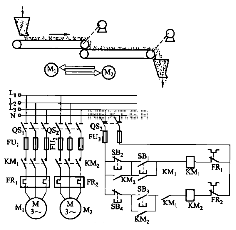
The circuit depicted in Figure 3-86 utilizes a line utilization time relay to control two motors, starting one before the other after an initial stall. The time relay KTi can be adjusted to modify the starting interval of the...
In the image above, Oscium's iMSO-104 oscilloscope is measuring the output waveform of an infrared receiver (IR Rx). The iPad and iMSO serve as the oscilloscope to measure the receiver's output signal as the alignment between the transmitter and...
This circuit is designed for speed control of small DC motors commonly found in devices such as electric drills, which are utilized for precision engineering and drilling tasks. The behavior of these motors, typically permanent magnet types, resembles that...
The LAN tester circuit can also test cables such as telephone, coaxial, LAN, and others. This circuit uses LEDs as the main indicator device. The LAN tester circuit is designed to verify the integrity and functionality of various types of...