
AD589-Dual Supply LVDT Signal Conditioner Design Procedure

The Linear Voltage Differential Transformer (LVDT) is a highly precise sensor commonly employed for measuring linear displacement. It operates based on the principle of electromagnetic induction, where a primary coil generates a magnetic field that induces voltages in two secondary coils. The differential voltage between these coils is proportional to the position of a movable core within the transformer, enabling accurate position sensing.
The AD589 integrated circuit is designed to facilitate the signal conditioning necessary for LVDT applications. This precision voltage reference provides a stable output voltage, which is essential for ensuring the accuracy of the LVDT measurements. The AD589 features low noise and low drift characteristics, making it suitable for high-precision applications where environmental factors may influence the sensor's performance.
In a typical LVDT application circuit, the LVDT is connected to the AD589 to amplify the differential output voltage. The output from the AD589 can be further processed using an analog-to-digital converter (ADC) for digital signal processing. This integration allows for the development of sophisticated control systems capable of providing real-time feedback on position changes, which is vital in various automation and robotics applications.
The combination of LVDT technology and the AD589 integrated circuit results in a robust solution for linear position sensing, offering high accuracy, reliability, and stability in diverse industrial environments.LVDT (linear voltage differential transformer) is widely used as linear position sensor. AD589 integrated circuit provides a complete solution for LVDT.. 🔗 External reference
Related Circuits
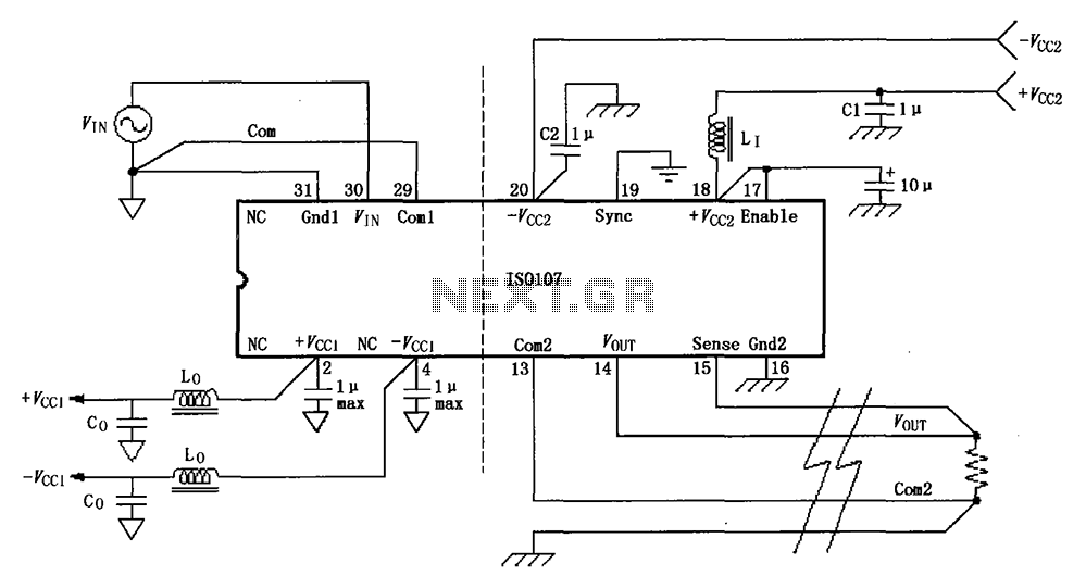
The basic connection circuit for the ISO107 signal and power supply is illustrated. Each power supply terminal must include a bypass filter. If the output current from the isolated power supply exceeds 15 mA, it is advisable to utilize...
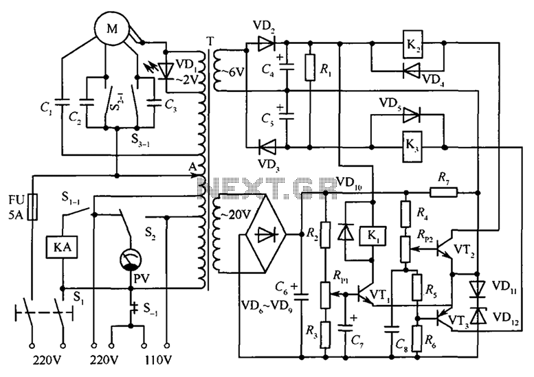
The circuit illustrated in the figure features an automatic voltage regulator (T) that utilizes a servo motor to ensure a constant output voltage. The transistors used are VT1 and VT2 (3DK9C, with a range of 65 to 85) and...
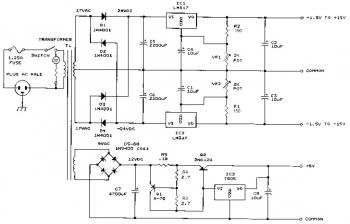
This bench power supply features three solid-state DC power supplies. The first supply provides an output of 1.5 to 15 volts at 1 ampere. The second supply offers a range of -1.5 to -15 volts at 1 ampere. The...
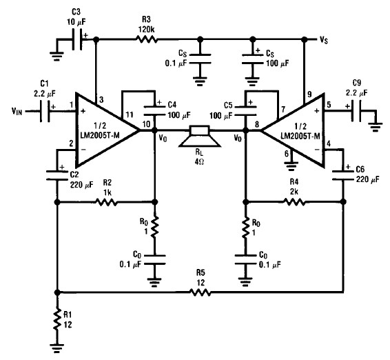
A simple 20-watt amplifier electronic project can be designed using the LM2005 dual high-power amplifier, which is engineered to provide optimal performance and reliability for automotive applications. The LM2005 20-watt amplifier has a high current capability of 3.5A, allowing...
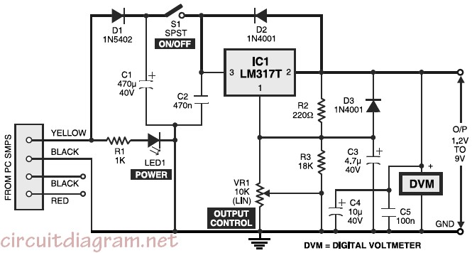
Variable desktop power supply that converts a high input voltage (12V) from the SMPS/PSU of a desktop computer into a small output voltage (1.25V to 9V). The variable desktop power supply is designed to provide adjustable output voltages ranging from...
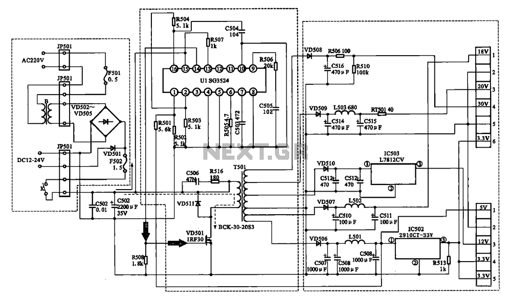
The Changhong DVB-2000 digital satellite receiver features a switching power supply circuit. This circuit primarily comprises a power input section, an oscillation switching circuit, and a DC output section. The power input circuit receives 22V AC from a step-down...