
Adaptive configuration LM317 adjustable power supply

The described adaptive adjustable power supply operates based on a feedback mechanism that optimally regulates voltage levels while reducing unnecessary energy loss. The LM317 voltage regulator is a key component, providing stable output voltage under varying load conditions. The switching circuit, consisting of the aforementioned components, plays a crucial role in determining the operational state of the power supply.
The operation begins with the relay K, which serves as a switch to alternate between two voltage regulation circuits. The presence of VW is critical; it acts as a voltage sensing element that determines whether the output voltage is below or above the threshold of 14V. When the output voltage is low, the relay remains inactive, allowing the circuit to draw power from the lower voltage (14V AC) source, which is efficient for minimal load conditions.
When the load increases and the output voltage rises above 14V, VW conducts, triggering VT2 to allow current flow. This action energizes relay K, switching the circuit to the higher voltage source (28V AC). This transition is smooth and automatic, ensuring that the power supply can handle varying load demands without manual intervention.
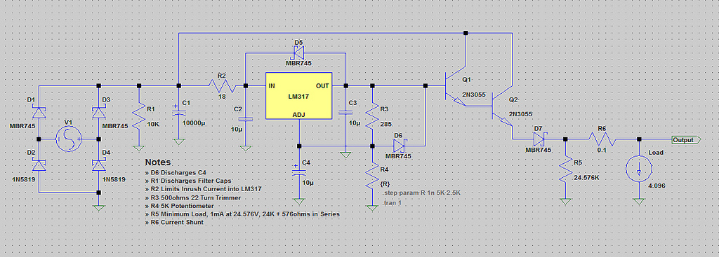
The design of the power supply emphasizes efficiency and adaptability, making it suitable for a range of applications where adjustable output voltage is required. The continuous adjustment feature offers versatility, enabling users to set the output voltage precisely as needed, whether for powering electronic devices, testing circuits, or other applications requiring stable voltage levels. The capability to deliver up to 3A of current further enhances the utility of this power supply in various electronic projects. As shown in FIG adaptive adjustable power supply. The power supply to the LM317 regulator device, adaptive switching circuit automatically switches the input voltage according to the output voltage level to reduce the input and output voltage of the differential pressure, reduce the power consumption of the power supply itself. Wherein VT2, VD5, VW, R5, R6, C10 and the relay K constitute adaptive switching operation circuit, when the output voltage Vo is lower than 14V, VW due to insufficient breakdown voltage is turned off, no current flows through, VT2 end, K does not move, the contacts K-1 is normally closed state, the transformer secondary 14V AC mains voltage regulator circuit.
Conversely, when the output voltage is greater than 14V, VW breakdown, VT2 conduction. K was electric, K-1 action, access to the 28V AC voltage regulator circuit. Thus ensuring the input and output pressure of no more than 15V. The output voltage of the circuit is 1.25 ~ 30V continuously adjustable, the maximum output current of 3A.
Related Circuits
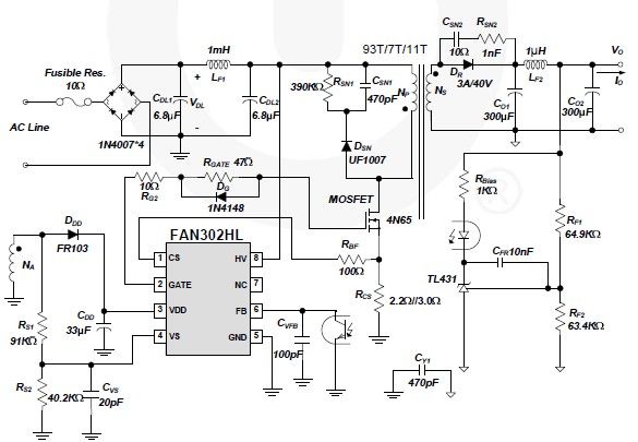
A simple 5-volt switching power supply electronic circuit project can be designed using the FAN302HL, a highly integrated PWM controller integrated circuit. This IC provides several features that enhance the performance of general flyback converters. The constant-current control of...
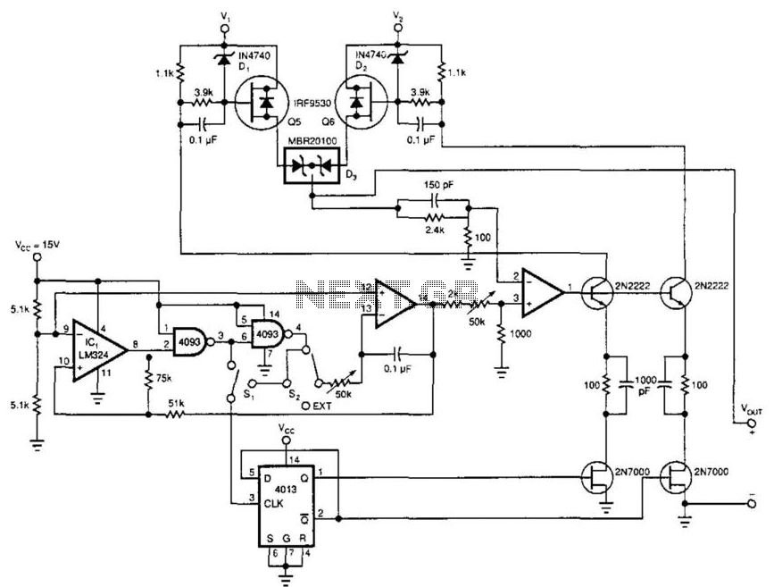
This power booster operates as a high-efficiency power multiplexer or, when supplied with an external signal source, as a high-power linear amplifier. For driving a load with a high-power square wave, the circuit alternately draws power from two external...
I didn't realize till the other day that I have never shown a circuit for a standard power supply. Shown below is a supply that will use any of the LM78XX series of voltage regulators. The transformer in the...
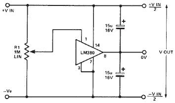
A simple split power supply circuit can be designed using the schematic diagram based on the LM380 audio power integrated circuit (IC). The output voltage regulation is dependent on the circuit feeding the LM380. The power dissipation is approximately...
The voltage range will be from 0V to 24V, and the current is not expected to exceed 4A. A microcontroller and an LCD could potentially be added to measure voltage and current. The schematic appears to be generally acceptable....
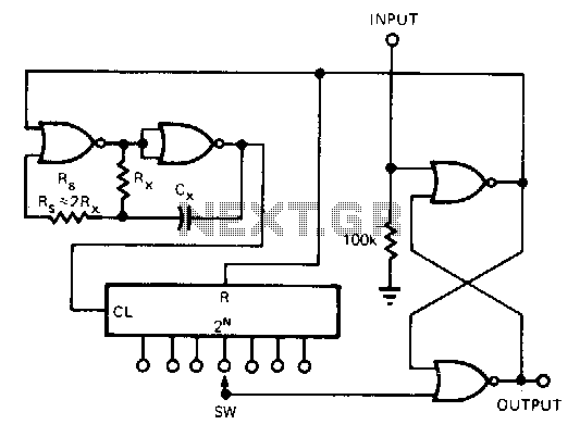
This CMOS circuit functions as a one-shot time delay switch and a general-purpose timer. It comprises a gated oscillator and a latch utilizing a CD4001 quad 2-input NOR gate, along with a CD4020 14-stage counter. The timing interval, TON,...