
Adaptor for 8 and 28 pin AVR

The described adaptor functions as a versatile interface for programming both 8-pin and 20-pin Dual In-line Package (DIP) devices using an In-System Programmer (ISP) in accordance with Atmel's AVR910 application note. The circuit is designed to supply the necessary power and clock signals to the target microcontroller while simultaneously powering the ISP.
In the 8-pin configuration, the device is aligned such that its pins correspond to specific positions on the programming socket. The 8 pins of the microcontroller connect to pins 1, 2, 3, 4, 17, 18, 19, and 20 of the socket. This arrangement ensures that the programming signals are correctly routed to the appropriate pins of the microcontroller. An important feature of this design is the inclusion of a Single Pole Single Throw (SPST) switch connected to pin 4. When programming an 8-pin device, the switch must be closed to ground pin 4, which is critical for proper operation during programming.
In contrast, when programming a 20-pin device, the circuit configuration changes. The same SPST switch must be opened to allow the oscillator crystal to function as the clock source for the target microcontroller. This change is essential as the 20-pin devices require the clock signal to be sourced from the crystal oscillator, ensuring accurate timing during the programming process.
The circuit likely includes additional components such as decoupling capacitors to stabilize the power supply, resistors for pull-up or pull-down functions, and possibly indicators like LEDs to show the status of the programming operation. Proper attention to layout and signal integrity is crucial to avoid issues during programming, especially considering the differing requirements of the two configurations.
Overall, this adaptor provides a practical solution for programming both 8-pin and 20-pin DIP devices, facilitating development and testing in embedded systems using Atmel microcontrollers.This adaptor lets me program 8 or 20 pin DIP devices using the In-System Programmer (ISP) described in Atmel's AVR910 application note. This circuit provides power and clocks for the part to be programmed and power to the ISP circuit. When programming 8 pin devices, the part is positioned toward pins 1 and 20 of the socket such that the 8 pins of the chip occupy the pins 1,2,3,4,17,18,19, abd 20 of the programming socket.In the case of an 8 pin part being programmed, the SPST switch that grounds pin 4 must to be closed.
Conversely, when programming a 20 pint part, the switch on pin 4 must be open so the crystal can be used for the clock for the part being programmed. 🔗 External reference
Related Circuits
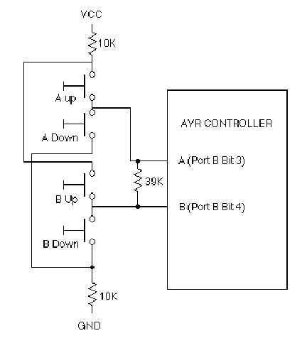
Just the solution for AVR applications in which I/O is tight, such as the ATtiny12. This should work well on other kinds of controllers that have independently controlled I/O direction registers, such as PIC and 6805 controllers. This solution...

This article continues from the previous one regarding the single character LCD display using an AVR microcontroller. The prior article demonstrated how to display a single letter on an LCD. This article advances the learning process by explaining how...
Here is an updated schematic featuring the RF Solutions receiver along with several minor additions. The design includes additional circuitry to manage the signals effectively. The updated schematic incorporates an RF Solutions receiver, which is essential for receiving radio frequency...

The most eloquent code in the history of embedded systems is rendered worthless without a means to execute it on the hardware. In embedded systems design, the execution of code on hardware is a critical aspect that determines the overall...
USB HID is a specification that encompasses devices such as mice and keyboards. It features a GPL-based driver that allows the implementation of USB on an AVR microcontroller without the need for specialized hardware. Additionally, there is the AVR309...

While owning a modern NiCd battery charger is advantageous, there may still be instances where an incompatible battery is encountered, such as one with an unusual voltage requirement or a need for a higher charging current than what a...