
Battery-Charging Indicator For Mains Adaptor

The described circuit utilizes a simple LED indicator to provide visual feedback on the charging status of a NiCd battery. The LED is connected in such a way that it lights up when the base-emitter voltage of the transistor reaches a threshold, indicating that current is flowing to the battery. A resistor is used to set the sensitivity of the circuit, allowing for adjustments based on the specific charging requirements. The choice of the BU406 transistor is significant due to its ability to handle high base currents, ensuring that the circuit remains operational even under higher charging conditions.
The circuit design should be implemented with careful attention to the power ratings of the components used, particularly the resistor and the transistor. The resistor value can be adjusted to tailor the current detection level, allowing for flexibility depending on the battery being charged. For practical applications, the LED should be mounted in a visible location, and the circuit should be housed in a protective enclosure to prevent accidental short circuits or damage.
This setup provides a straightforward solution for charging incompatible batteries while ensuring that the user is aware of the charging status through the LED indicator. It balances simplicity and effectiveness, making it a viable option for those who require a custom charging solution.Although you may well be the proud owner of the very latest NiCd battery charger, you may still come across the odd `incompatible` battery, for example, one having a rare voltage or requiring a much higher charging current than can be supplied by your off-the-shelf charger. In these cases, many of you will resort to an adjustable mains adaptor (sa y, a 500-mA type) because that is probably the cheapest way of providing the direct voltage required to charge the battery. Not fast and not very efficient, this `rustic` charging system works, although subject to the following restrictions: You should have some idea of the charging current.
In case you use an adaptor which is adjustable but of the unregulated, low output current type, you can adjust the current by adjusting the output voltage. You have to know if the current actually flows through the battery. A current-detecting indicator is therefore much to be preferred over a voltage indicator. To prevent you from forgetting all about the charging cycle, the indicator should be visible from wherever you pass by frequently.
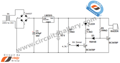
Using the circuit shown here, the LED lights when the baseemitter potential of the transistor exceeds about 0. 2 V. Using a resistor of 1 as suggested this happens at a current of about 200 mA, or about 40 mA if R1 is changed to 4.
7. The voltage drop caused by this indicator can never exceed the base-emitter voltage (UBE) of the transistor, or about 0. 7V. Even if the current through R1 continues to increase beyond the level at which UBE = 0. 7 V, the base of the transistor will `absorb` the excess current. The TO-220 style BU406 transistor suggested here is capable of accepting base currents up to 4A. Using this charging indicator you have overcome the restrictions 2 and 3 mentioned above. 🔗 External reference
Related Circuits
This battery allows the indicator to the car battery voltage monitor. The indicator has four LEDs which indicate power. The more LEDs, the higher the voltage. The last LED is a flashing LED. It comes on when the accuspaning...
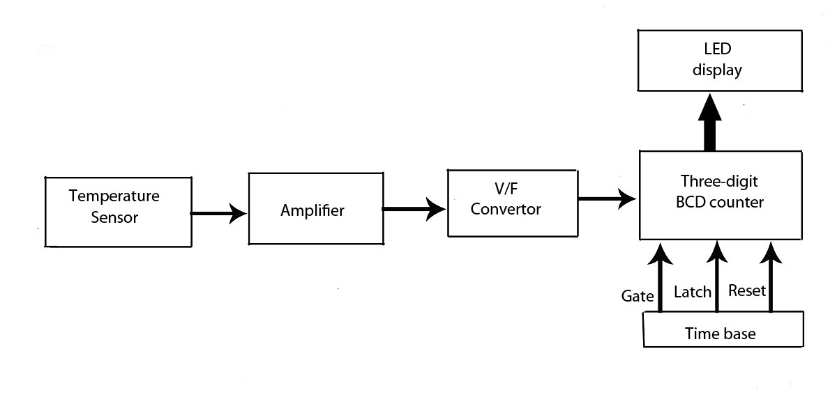
This verified project provides an idea, circuit, and operation of the LED display temperature indicator. It features a digital temperature indicator utilizing a voltage-to-frequency (V/F) converter, along with various electronic projects. The LED display temperature indicator is designed to provide a...
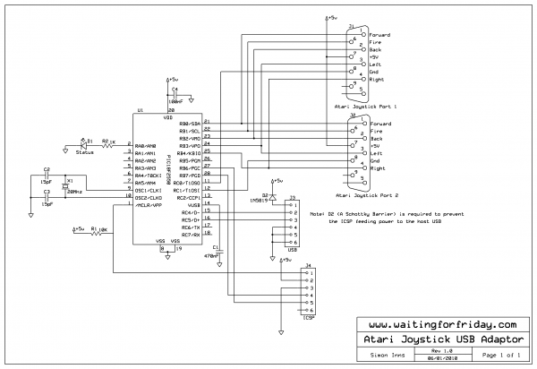
This project implements a composite USB device that supports two USB 2.0 full-speed gameport HID interfaces. The physical joystick ports are wired according to the Atari standard, allowing the connection of most Commodore 64 and Amiga joysticks, as well...
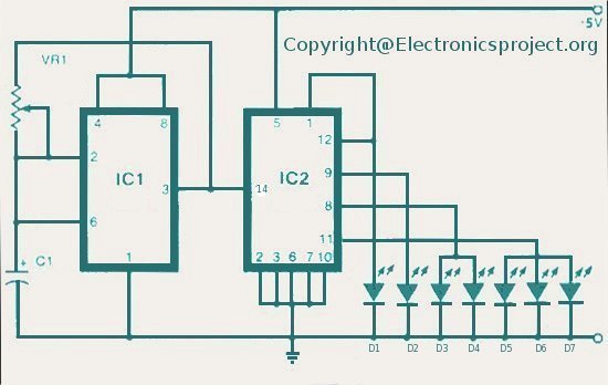
The LED indicator in this project can be used for bike indicators or car direction indicators. A 555 timer and a BCD 7490 are utilized along with several resistors, exceeding 100 in total across various electronic projects. The circuit employs...
This is a straightforward 12V rechargeable smart battery charger circuit. It can be utilized as a charger for car batteries, inverter batteries, emergency light batteries, and more. An automatic indicator alarm circuit accompanies this battery charger schematic. The primary...
The above circuit is a precision voltage source and contains a temperature sensor with a negative temperature coefficient. Meaning, whenever the surrounding or battery temperature increases, the voltage will automatically decrease. The temperature coefficient for this circuit is -8mV...