
How to display text on 16x2 LCD using AVR microcontroller (ATmega16)
")
The schematic for connecting an LCD to the ATmega16 microcontroller involves several key components and connections. The LCD typically used is a 16x2 character display, which allows for the display of two lines of 16 characters each. The interface between the LCD and the microcontroller is primarily established through a parallel data bus.
The connections begin with the power supply. The VSS pin of the LCD is connected to the ground (0V), while the VDD pin is connected to a positive voltage supply, typically +5V. The V0 pin, which controls the contrast of the display, is connected to a potentiometer that allows for adjustment of the contrast level.
The RS (Register Select) pin is crucial as it determines whether the data being sent to the LCD is command data or character data. This pin is connected to a digital output pin of the ATmega16 microcontroller. The RW (Read/Write) pin is usually grounded for write operations, allowing the microcontroller to send data to the LCD. The E (Enable) pin is also connected to a digital output pin of the microcontroller and is used to latch the data into the LCD.
For data transmission, the D0 to D7 pins of the LCD are connected to the corresponding data pins on the ATmega16. Typically, a 4-bit mode is used for communication, which means that only D4 to D7 will be utilized for data transfer, while D0 to D3 are left unconnected.
Once the hardware connections are established, the software implementation involves initializing the LCD, setting it to 4-bit mode, and sending commands to configure the display. The process to display a string involves iterating through each character of the string and sending it to the LCD's data pins, followed by toggling the Enable pin to latch the data.
The overall process not only enhances the understanding of interfacing an LCD with a microcontroller but also illustrates the fundamental principles of data communication in embedded systems. Displaying strings on an LCD is a vital skill in creating user interfaces for various electronic applications, ranging from simple displays to complex control systems.This article is in continuation to the articleSingle character LCD display using AVR. The aforesaid article shows how to display a single letter onLCD. Moving forward towards learning to work with LCD, this article explains how to display a string on LCD. Displaying string is occasionally used in many applications. The connection of the LCD with t heAVR microcontroller(ATmega16) is shown in the circuit diagram. A string is nothing but a sequence of characters. The following steps explain how to display a string on the LCD. 🔗 External reference
Related Circuits
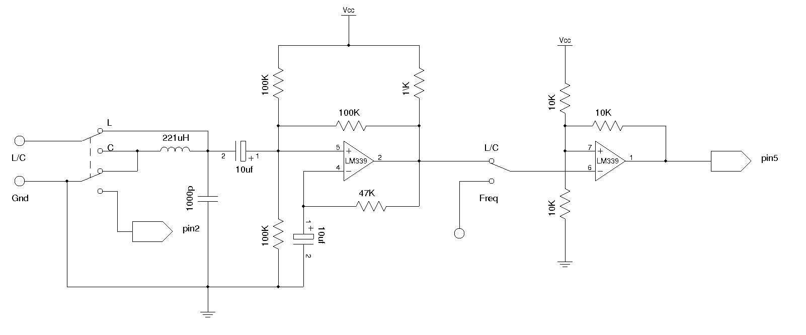
An LC meter is being constructed due to the absence of a multimeter capable of measuring inductance. Although the available multimeters can measure capacitance, they lack accuracy for small capacitance values in the range of several picofarads (pF). While...

This circuit represents a remote control unit that utilizes radio frequency signals to operate various electrical appliances. The remote control unit features four channels, which can be expanded to twelve. This circuit stands out from similar designs due to...
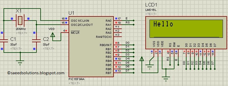
This post presents the LCD interfacing code utilizing the PIC16F84A microcontroller. The code is developed in the C programming language using MPLAB with the HI-TECH C compiler. The interfacing of an LCD (Liquid Crystal Display) with the PIC16F84A microcontroller...
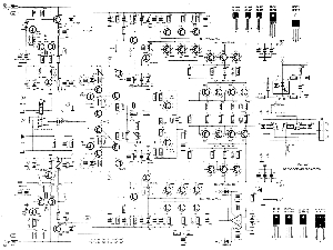
The following circuit illustrates a 2000W Power Amplifier Circuit Diagram. This circuit utilizes the BC560C transistor. Features include a robust design. The 2000W power amplifier circuit is designed to deliver high output power suitable for various applications, including audio amplification...

Utilize the Maxim MAX292 switched-capacitor filter integrated circuit to convert a square wave into a sine wave. The operational frequency range of the circuit spans from 5.2282 Hz to 8928.6 Hz when the microcontroller is functioning at a 16-MHz...
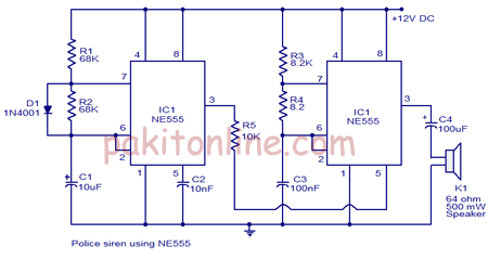
The circuit diagram of a police siren utilizes two NE555 timer integrated circuits (ICs), each configured as an astable multivibrator. It can operate with a power supply ranging from 6 to 15V DC and produces a loud sound. An...