
Gyrator Circuit
Gyrators serve a critical role in the design of DC holding circuits within Data Access Arrangements (DAAs). These circuits are essential for maintaining the integrity of the connection when the telephone is off-hook. The primary challenge arises from the use of dry transformers, which are unsuitable for DC current due to their construction. To address this limitation, a gyrator can be employed as a viable alternative.
In the circuit design, resistors R1 and R2 are carefully selected to regulate the flow of DC current, ensuring that it remains within the desired parameters. Capacitor C1 acts as a high-pass filter, effectively attenuating any high-frequency signals that may interfere with the operation of the circuit. The design incorporates transistor Q1, whose base-emitter current is maintained at a constant level. This stability is crucial as it directly influences the output of transistor Q2, which is designed to provide a consistent output regardless of fluctuations in the input signal.
The gyrator's unique properties allow the circuit to behave inductively, effectively blocking high-frequency signals while permitting the necessary DC current to flow. This characteristic is particularly advantageous in telephone applications where signal integrity is paramount. Furthermore, the bridge configuration included in the design guarantees that the circuit operates correctly, regardless of the input polarity. This feature is significant in telephone systems, where the tip and ring connections can be inadvertently reversed.
Overall, the integration of gyrators in DC holding circuits not only enhances performance but also ensures reliability in telecommunications applications. The careful selection of components and the thoughtful design of the circuit contribute to its effectiveness in managing DC currents while maintaining signal integrity.Gyrators find application in DC holding circuits which are used in most DAAs (Data Access Arrangements). DAAs typically use dry transformers which can not tolerate DC current, and incorporate a DC blocking cap.
When the telephone goes off hook, it must pass DC current, and so an inductor can be used, which defeats the purpose of using a dry transformer, or a gyrator can be used. R1 and R2 are adjusted so that just the right amount of DC current flows. C1 creates a filter which attenuates any high frequencies to the base of Q1. Since the base to emitter current of Q1 is held constant, output of Q2 is held constant and the circuit looks inductive because it doesn`t pass high frequencies. The bridge is to guarantee that the circuit is powered with the correct polarity, regardless of the input polarity.
Tip and ring on a telephone circuit can often be reversed. Do you need help with an electronics design Daycounter provides contract electronics design services. Contact us to give you a quote on your electronics design project. 🔗 External reference
Related Circuits
This is an efficient 4-stage stabilized power supply unit designed for testing electronic circuits. It delivers well-regulated and stabilized output, which is crucial for most electronic circuits to function correctly. The circuit includes an audio-visual indicator that activates in...

A resistor R1, capacitor C1, and two converters create a square wave generator that produces a fundamental tone. This generator is followed by an inverter that functions as both a buffer and a driver for the system. Resistor R2,...
The delay time ranges from 0.5 to 3.5 seconds, which can be adjusted using the potentiometer RP to modify the delay duration. The circuit utilizes a timing mechanism that allows for the adjustment of delay intervals between 0.5 seconds and...

The Meter Ml is a +/-50-uA zero-center D'Arsonval meter movement driven by Ul, a TL081 FET op amp, through R3. The gain of Ul is set to 11 using resistors R1 and R2, while capacitor C1 restricts the bandwidth...

A single pulse signal generating circuit is depicted, which utilizes switch contacts to create a digital signal for reset or stop functions. This one-shot pulse generating circuit operates as a non-synchronous differential circuit. The single pulse signal generating circuit, commonly...
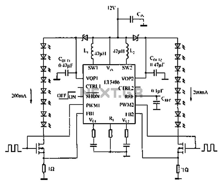
The automotive LED driver circuit diagram utilizes the LT3486. The LED is employed in the car's central high-mounted stop lamp (CHMSL), providing advantages such as faster achievement of the set brightness, higher efficiency, longer lifespan, and simplified design and...
Warning: include(partials/cookie-banner.php): Failed to open stream: Permission denied in /var/www/html/nextgr/view-circuit.php on line 713
Warning: include(): Failed opening 'partials/cookie-banner.php' for inclusion (include_path='.:/usr/share/php') in /var/www/html/nextgr/view-circuit.php on line 713