
Small Metal detector schematic circuit

The metal detector circuit operates on a simple principle of frequency modulation, utilizing a combination of capacitors, inductors, and a transistor to detect changes in the electromagnetic field caused by nearby metallic objects. The circuit is powered by a 9-volt DC supply, which can be sourced from either a battery or an external power supply.
The variable capacitor, C1, has a capacitance range of up to 365 pF, allowing for fine-tuning of the oscillator frequency. This is crucial for achieving the desired detection sensitivity. The fixed capacitors, C2, C3, and C4, serve specific roles in the circuit. C2, a 100 pF silver mica capacitor, is typically used for stability in high-frequency applications, while C3, a 0.05 uF disc capacitor, may be used for coupling or bypassing, ensuring that unwanted frequencies do not affect the circuit's operation. C4, with a capacitance of 4.7 uF, is likely employed for power supply filtering, smoothing out any voltage fluctuations that could interfere with the circuit's performance.
The transistor Q1, an RCA SK3011 or an equivalent NPN type, acts as an amplifier and is essential for processing the signals generated by the oscillator. The choice of a ½-watt resistor rating throughout the circuit ensures that the components can handle the power levels without overheating, contributing to the circuit's reliability.
The L1 coil, which is a critical component of the metal detector, consists of 18 turns of 0.65 mm enameled wire wound on a 4-inch diameter form. This coil acts as an inductor and is responsible for generating the electromagnetic field. When a metallic object enters this field, the inductance of the coil changes, which in turn alters the frequency of the oscillator. This frequency shift produces a beat tone in the radio receiver, indicating the presence of metal.
The overall design of this metal detector circuit is straightforward, making it suitable for hobbyists and educational purposes, while also demonstrating fundamental electronic principles such as resonance, oscillation, and signal detection.This metal detector circuit needs to be powered using a 9 volts power supply ( DC) or a 9 volts battery . The C1 capacitor is a variable capacitor with a value of 365 pF , C2 is a 100pF silver mica capacitor , C3 is a 0.05 uF disc capacitor and the C4 is a 4.7 uF capacitor .
The Q1 transistor can be RCA SK3011 npn transistor or equivalent type and all resistors need to be ½ watts . This metal detector schematic circuit is based on a transistor radio as an detector . With the radio tuned to a weak station you must adjust the variable capacitor C1 until the locator oscillator beats against the received signal . If a metal is detected the inductance of the L1 coil is changed , changing the frequency of the locator oscillators , resulting a change in the beat tone radio .
The L1 search coil of the metal detector circuit must have 18 turns from a 0.65 mm enameled wire scrambled on a 4 inch diameter support . 🔗 External reference
Related Circuits
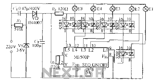
The Shenzhen Skywave Semiconductor Co., Ltd. produces a five-flash integrated circuit controller known as M1500P. This device is manufactured using a DIP 14 standard package and can be customized according to customer specifications for soft seal packaging. It operates...
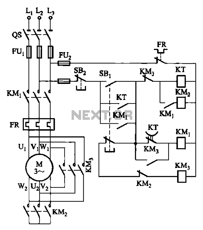
The circuit depicted in Figure 3-41 illustrates a Y-transfer process. When contact KMi is turned off, the motor undergoes a transition in the event of a power failure. Additionally, the main contact KM3 is disconnected when KM2 is activated,...

This is a low-cost FM antenna booster designed to enhance reception of programs from distant FM stations. The FM antenna booster circuit features a common-emitter tuned RF preamplifier utilizing the VHF/UHF transistor 2SC2570 (C2570). The schematic illustrates the configuration...
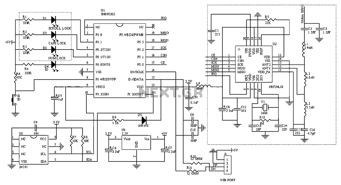
The circuit diagram for the receiving portion of a 2.4 GHz wireless keyboard is presented below. The 2.4 GHz wireless keyboard receiving circuit typically consists of several key components that work together to receive and process signals transmitted from the...
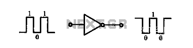
A common-emitter transistor amplifier produces an output signal that is 180 degrees out of phase with the input signal, commonly referred to as an inverting amplifier. When the electrical path for amplifying the pulse signal is activated, this circuit...
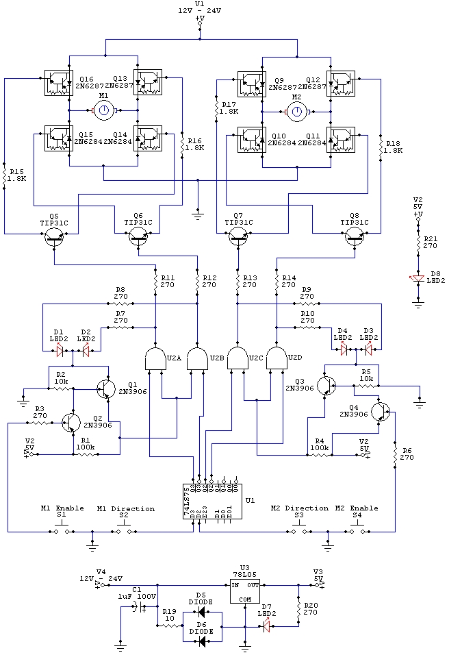
The wiring schematic played a significant role in the robot. This diagram is used to graphically display all the wiring of the motor-controlling micro-components that enabled the robot to physically move forward, backward, left, right, and stop. This diagram...