
Adjustable 1.3-22V Regulated Power Supply

The Adjustable Power Supply circuit typically utilizes a linear voltage regulator or a switching regulator to achieve the desired output voltage. The primary components of this circuit include a transformer, a rectifier, a filter capacitor, and an adjustable voltage regulator such as the LM317 or a similar device.
The transformer steps down the AC mains voltage to a lower AC voltage suitable for rectification. Following the transformer, a bridge rectifier converts the AC voltage to a pulsating DC voltage. A smoothing capacitor is then employed to filter out the ripple, providing a more stable DC voltage.
The adjustable voltage regulator is connected to the output of the smoothing capacitor. The output voltage can be adjusted by varying the resistance in the feedback loop of the regulator, typically using a potentiometer. This allows for a range of output voltages to be selected based on the requirements of the application.
Additional components may include bypass capacitors to improve transient response and stability, as well as heat sinks for the voltage regulator to dissipate heat generated during operation. Proper layout and grounding practices should be followed to minimize noise and ensure stable operation.
This Adjustable Power Supply is suitable for various applications, including powering electronic circuits, testing, and prototyping, making it an essential tool for engineers and hobbyists alike.Want a regulated voltage that can be adjusted to suit your application? This Adjustable Power Supply is small, easy to build and can be adapted to produce.. 🔗 External reference
Related Circuits

Voltage is transformed by the transformer turns ratio N2/N1. For instance, if a 20VAC secondary voltage is required with a 120VAC input, a 6:1 ratio would be needed. When full load current is drawn from the secondary winding, the...
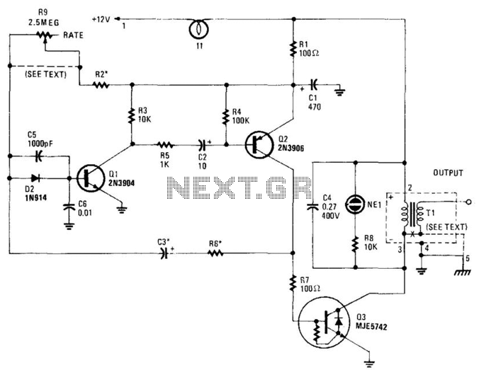
This high-voltage pulse supply generates pulses up to 30 kV. Q1 and Q2 form a multivibrator in conjunction with peripheral components R1 through R6, and C1, C2, C3, C5, C6, and D2. R9 adjusts the pulse repetition rate, while...
This circuit clearly indicates the supply voltage level in a larger device. When the indicator receives a stable 12 volts, LED1 emits a steady yellow light. If the input voltage drops below 11 volts, LED1 begins to blink, with...
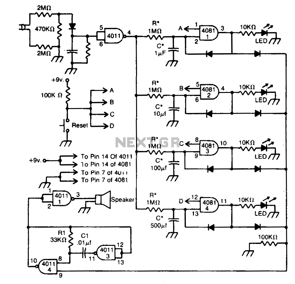
This circuit indicates that a power outage occurred for 1, 10, 100, and 500 seconds based on the values provided for R* and C*. After a power failure, the circuit can be reset by pressing the Reset button. The described...
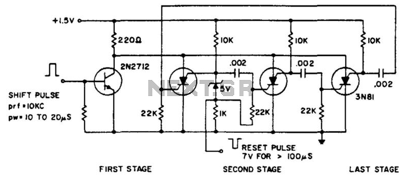
The ring counter operates from 1.0 to 6.0 V and requires only 6 mW at 1.5 V. The reset pulse activates the first stage with its trailing edge. The maximum shift pulse width increases with voltage and approaches 70...
The following circuit illustrates the BUZ902DP 300 Watt Audio Power Amplifier Circuit Diagram. Features include audio frequency linearity from 20 Hz to 20 kHz. The BUZ902DP is a high-performance audio power amplifier designed to deliver up to 300 watts of...