
Power failure detector

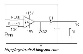
The described circuit functions as a power outage indicator, utilizing a timing mechanism to signal the duration of an outage. The timing is determined by the resistor (R*) and capacitor (C*) values, which create a time constant that governs how long the circuit remains active after power is restored. The circuit is designed to provide visual or audible feedback corresponding to the specific duration of the outage, allowing users to understand the length of the interruption.
When a power failure occurs, the capacitor begins to discharge through the resistor, and the voltage across the capacitor will decrease over time. The circuit may include a microcontroller or a simple comparator that monitors the voltage level. Depending on the threshold set within the circuit, different output signals can be activated for each specified duration of the outage—1 second, 10 seconds, 100 seconds, and 500 seconds.
The Reset button serves as a manual control to clear the circuit’s state and prepare it for future power outages. When pressed, it reinitializes the system, allowing it to start monitoring for power interruptions again. This feature ensures that the circuit does not retain the previous state after a reset, thus providing accurate and reliable performance.
Additional components may include LEDs for visual indication or a buzzer for an audible alert, depending on the design requirements. The schematic would typically include a power supply section, the timing circuit composed of R* and C*, the reset mechanism, and the output indicators. Proper selection of R* and C* values is crucial for achieving the desired timing intervals and ensuring the circuit operates within the specified parameters.This circuit indicates that a power outage occured for 1, 10, 100, and 500 seconds with the values given for R* and C* After a power failure, the circuit can be reset by pushing the Reset button.
Related Circuits
The circuit presented includes resistors of 10k ohms and capacitors of both 1µF and 10µF. There is also a diode included in the schematic. Assistance is requested for corrections to achieve the desired output. The circuit design consists of a...
The LM317 is capable of providing extremely good load regulation, but a few precautions are needed to obtain maximum performance. For best performance, the programming resistor (R1) should be connected as close to the regulator as possible to minimize...
A single chip metal detector with a range of a few inches. This is useful for detecting nails or screws in walls and floors, or for locating buried mains cable. The heart of the circuit is a single IC,...

A power supply typically consists of a transformer, rectifier, filter, adjustment components, and reference power supply and sampling circuits. Additionally, it may include overload or short circuit protection devices. The circuit begins with a 220V step-down transformer (T) that...
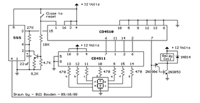
When the switch is opened, the timer generates an approximate 1-second clock signal, decrementing the counter until it reaches a count of zero. Upon reaching zero, the carry-out signal at pin 7 of the counter goes low, energizing a...
This document describes how to construct a dual polarity linear power supply which can be configured for any positive or negative voltage between 1.2-35V. A power supply is the fundamental building block of all but the simplest of electronic...