
High-Voltage Pulse Supply

This high-voltage pulse supply circuit is designed for generating high-voltage pulses, specifically up to 30 kV, which can be utilized in various applications such as igniting gas burners or other high-voltage triggering scenarios. The core of the circuit consists of a multivibrator configuration formed by transistors Q1 and Q2, which oscillate to produce a square wave output. The frequency of this oscillation is controlled by the resistor network consisting of R1 through R6 and the capacitors C1, C2, C3, C5, and C6.
Resistor R2 plays a crucial role in determining the maximum pulse repetition rate, which is limited to 20 Hz. This is particularly important in applications where excessive pulse rates could lead to component stress or undesired circuit behavior. Adjusting R9 allows for fine-tuning of the pulse repetition rate, providing flexibility in operation. However, in scenarios where a fixed pulse rate is preferred, R9 can be omitted, and the selection of R2 becomes critical, with a starting value of around 1 ohm being recommended for initial testing.
The inclusion of a type 1156 lamp (I1) as a current limiter is essential for protecting the circuit from excessive current flow, which could potentially damage sensitive components. This lamp serves as a visual indicator of current flow, enhancing the safety and functionality of the circuit.
Transistor Q3 functions as both a power amplifier and a switch, driving T1, which is an automotive ignition coil. This coil is responsible for stepping up the voltage generated by the multivibrator to the high levels required for the application. The output from the ignition coil can be used to generate high-voltage pulses necessary for ignition or triggering high-voltage devices.
The circuit also incorporates NE1 as a pulse indicator, providing a visual cue that the circuit is operational and generating pulses. This is particularly useful for troubleshooting and ensuring that the circuit is functioning as intended.
Given the high-voltage capabilities of this circuit, it is imperative to adhere to strict construction techniques and safety precautions. Proper insulation, secure connections, and adequate spacing between high-voltage components are vital to prevent accidental discharges and ensure safe operation. Additionally, operators should utilize appropriate personal protective equipment (PPE) when working with or testing this circuit to mitigate the risks associated with high-voltage systems. This high-voltage pulse supply will generate pulses up to 30 kV. Ql and Q2 form a multivibrator in conjunction wi th peripheral components Rl through R6 and CI, C2, C3, C5, C6, and D2. R9 adjusts the pulse repetition rate. R2 should be selected to limit the maximum repetition rate to 20 Hz. II is a type 1156 lamp used as a current limiter. R9 can be left out and R2 selected to produce a fixed rate, if desired. Try about 1 as a start. Q3 serves as a power amplifier and switch to drive Tl (an automotive ignition coil). NE1 is used as a pulse indicator and indicates circuit operation. Because this circuit can develop up to 30 kV, suitable construction techniques and safety precautions should be observed.
Related Circuits
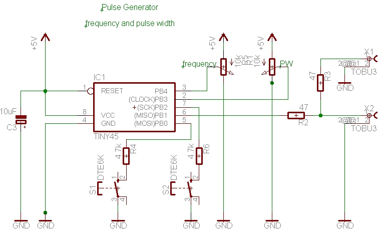
A simple pulse generator with a variable duty cycle and frequency is often useful in the lab to trigger or test other devices, such as a servo with a frequency of 50 Hz and pulses between 1 and 2...
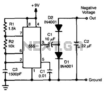
By utilizing a 555 timer to produce a square wave and employing a voltage-doubling technique on the output, a negative voltage that is nearly equivalent to the positive supply can be achieved. The available current ranges from 20 to...
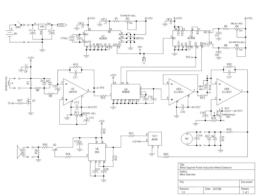
As you can see, there is only one regulated 12 volt supply operating the entire circuit. This allowed me to adjust the offset within an operating window. By using a tantalum capacitor of reasonably high capacity, the signal passes...
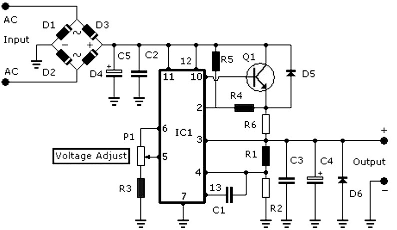
DC power supply 3-30V 3-30V 3A stabilized power supply. Go to that page to read the explanation about the above power supply related circuit diagram. The DC power supply described is a versatile device capable of providing a stable output...
This project is offered totally free for those who are interested in it. I have tried to make this article as complete as possible, but I will not assume any liability for any errors or omissions in this article....
Amateur Radio Transmitters using valves such as 807 or 1625 works well with a plate voltage between 600V to 700 Volts. The circuit described here is a full wave voltage doubler. The output voltage is twice the input voltage....